
Cable trays carry the power, control, and data cabling that keep a facility running. But the tray itself is only as reliable as the support system holding it in place. Selecting the right support spacing, bracket type, and seismic bracing is what prevents tray sag, joint separation, and cable damage during normal operation or an earthquake. A well-engineered support system is therefore as important as the tray selection itself.
What Is a Cable Tray Support System?
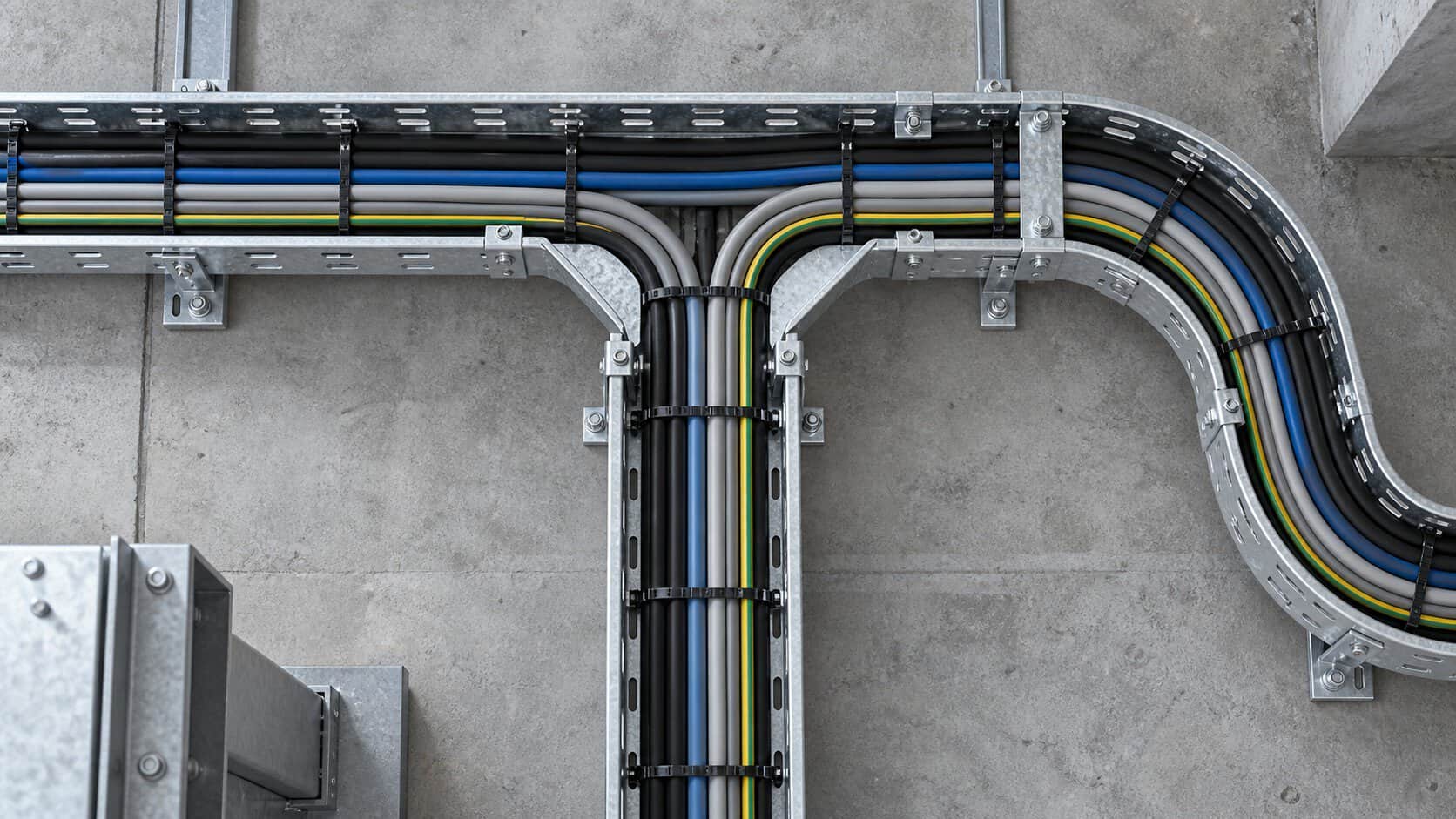
A cable tray support system includes the brackets, trapezes, threaded rods, channel sections, clamps, and fasteners that attach the cable tray to the building structure. The system must carry the dead load of the tray plus cables, live loads from installation and maintenance, and environmental loads such as wind and seismic forces. Support design is covered by NEMA VE 1, IEC 61537, and national codes such as NFPA 70 (NEC Article 392) and the building seismic standards ASCE 7 in the United States and GB 50981 in China.
How Support Loads Are Transferred
Cable tray is a beam-like element that spans between support points. The weight of the tray and cables creates bending moment and shear force at the supports. If the span is too long, the tray will deflect excessively, stressing cable jackets and connector terminations. The support system transfers these loads into the building structure — beams, columns, walls, or dedicated overhead steel — and must be verified by the structural engineer where loads are significant.
Types of Cable Tray Supports
Wall Brackets
Wall brackets extend from a vertical surface to support the side rail of the tray. They are common where trays run along corridors, tunnels, or equipment rooms. Bracket spacing and embedment depth must match the wall material and expected load.
Trapeze Hangers
A trapeze support consists of two threaded rods suspended from overhead structure with a horizontal channel or angle spanning between them. Trapezes are versatile and allow multiple tray runs to share the same support structure.
Cantilever Brackets
Cantilever arms extend from a vertical column or wall to carry a single tray width. They are economical for straight wall runs and are often used in industrial plants and tunnels.
Floor-Mounted Stanchions
Floor stanchions support tray runs where overhead attachment is not possible, such as in cable tunnels or beneath raised floors. The stanchion must be anchored to the slab and checked for overturning under cable load.
Seismic Bracing
Seismic braces restrain the tray against horizontal movement during an earthquake. Longitudinal braces run parallel to the tray, transverse braces run perpendicular, and sway braces limit lateral motion. Bracing spacing is specified in seismic codes and depends on the seismic design category and building importance factor.
Cable Tray Support Comparison
| Support Type | Best Use | Load Capacity | Seismic Suitability |
|---|---|---|---|
| Wall bracket | Corridor and wall-mounted runs | Low to medium | Good with anchors |
| Trapeze hanger | Ceiling suspension, multiple trays | Medium to high | Good; easy to add sway bracing |
| Cantilever arm | Straight industrial wall runs | Medium | Moderate; depends on embedment |
| Floor stanchion | Tunnels, no overhead structure | Medium to high | Good if base anchored |
| Seismic brace assembly | High seismic zones, critical loads | As designed | Required |
Span, Load and Deflection
Manufacturer span tables give the maximum support spacing for a given tray width, loading class, and allowable deflection. Loading classes in IEC 61537 are typically expressed as a uniformly distributed load in N/m, and common values include 75, 150, 300, and 600 N/m. Deflection limits are usually span/200 or span/100 depending on the standard and application.
When cable density is high, calculate the actual load per meter from the weight of cables, not just the tray. For power cables, manufacturer datasheets give weight per meter; add a safety factor for future cables and installation personnel.
Typical Applications
Data Centers
Data centers use dense cable trays suspended from the ceiling. Support spacing is often shorter than the maximum to limit vibration and allow future cable additions. Seismic bracing is mandatory in many jurisdictions.
Industrial Plants
Industrial cable tray runs can be hundreds of meters long and carry heavy power cables. Trapeze and cantilever supports are common, and seismic bracing is designed to the plant’s seismic category.
Commercial Buildings
Commercial installations typically use lighter-duty trays and wall brackets. Careful coordination with HVAC, sprinklers, and ceilings is needed to keep trays accessible for future modifications.
Tunnels and Underground
Tunnel cable supports must resist humidity, corrosion, and limited access. Hot-dip galvanized or stainless steel supports are standard, and floor stanchions are often used where ceiling mounting is impractical.
How to Select Cable Tray Supports
- Calculate the total load. Include tray weight, cable weight, a future capacity allowance, and personnel loading where applicable.
- Choose support spacing. Use manufacturer span tables and reduce spacing where deflection or vibration is a concern.
- Match support capacity. Each bracket or trapeze must carry the load between two spans, which is approximately the load per meter times the span length.
- Check structure capacity. Verify that the building structure can accept the concentrated loads at support points.
- Add seismic bracing. In seismic zones, add longitudinal and transverse bracing per ASCE 7 or GB 50981 requirements.
- Select corrosion protection. Hot-dip galvanizing is standard for indoor industrial use; stainless steel or epoxy coatings are used outdoors or in corrosive environments.
- Plan access. Maintain clearance above and below trays for future cable pulling and inspection.
Quality Inspection Before Acceptance
- Check support spacing against approved drawings and manufacturer span tables.
- Verify all fasteners are tightened to the specified torque and that hardware matches the corrosion-protection specification.
- Inspect welded or threaded rod supports for cracks, stripped threads, or damaged coatings.
- Confirm seismic braces are installed at the required locations and are positively attached to structural elements.
- Measure tray deflection under full cable load; compare against the specified limit.
- Ensure metallic trays are continuously bonded and grounded, not relying on bolted joints alone.
Supplier Evaluation Checklist
- Does the supplier provide load-span tables and seismic bracing details for the tray and support system?
- Are supports available in galvanized steel, stainless steel, or aluminum to match the environment?
- Can the supplier provide structural calculations or drawings stamped by a qualified engineer?
- Are seismic brackets, channel nuts, and clamps supplied as a complete system rather than generic hardware?
- Is installation guidance available, including recommended torque values and bonding methods?
Frequently Asked Questions
1. How far apart should cable tray supports be?
Support spacing depends on tray width, type, and load class. Typical spans range from 1.5 m to 3 m for ladder and perforated trays. Always follow the manufacturer’s span table for the specific load.
2. Do cable trays need seismic bracing?
In seismic design categories where non-structural components require restraint, cable trays must be braced longitudinally and transversely. The exact requirements are defined by ASCE 7, GB 50981, or the applicable local seismic code.
3. Can cable tray be supported from threaded rod alone?
Threaded rod is commonly used with trapeze hangers, but the rod diameter and embedment depth must be engineered for the load. Anti-rotation washers and proper anchoring are essential.
4. What is the maximum allowable tray deflection?
Common limits are span/100 or span/200 under full load, depending on the standard and the sensitivity of the cables. Always confirm with the project specification.
5. Should power and data cables share the same support?
They can share the same support structure if separated by a solid divider or installed on separate trays. Separation reduces electromagnetic interference and protects low-voltage circuits.
6. How are cable trays grounded?
Metallic tray sections are bonded with grounding jumpers at every joint and connected to the main earthing terminal. Do not rely on bolted connections alone for continuity.
7. What coating is best for outdoor cable tray supports?
Hot-dip galvanizing is the minimum for outdoor use. For coastal or chemically aggressive environments, stainless steel or epoxy-coated steel provides better corrosion resistance.
Complete Cable Management Solutions from BANGE Electric
BANGE Electric supplies cable tray systems and matching support components for commercial, industrial, and infrastructure projects. Our product range includes ladder, perforated, and solid-bottom trays with galvanized, stainless steel, and aluminum finishes, plus brackets, trapezes, and seismic bracing hardware sized to the project load.
Contact BANGE Electric with your specifications for a quotation and delivery schedule.
Requirements may vary by application, market, and applicable standard. Final specification should be confirmed with the engineering team.