
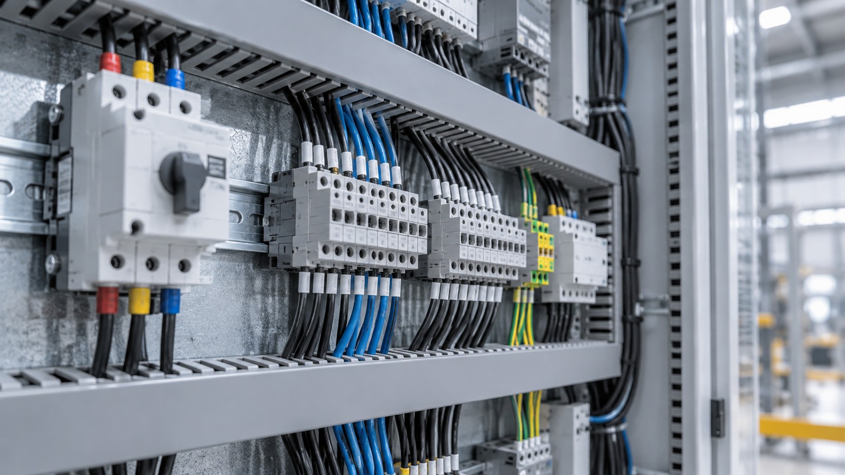
A busway tap-off unit (also called a plug-in box or tap box) is the device that draws power from a busway run at a specific point and delivers it to a downstream load or sub-panel. It clamps onto the busway housing, contacts the conductors through a plug-in interface, and houses the protective device — typically an MCCB, fuse switch, or isolator. Tap-off units are what make busway a flexible distribution system rather than a fixed trunk, because outlets can be added, moved, or resized without touching the main run.
What Does a Tap-Off Unit Actually Do?
A busway carries current along continuous conductors inside a metal housing. Somewhere along that run, a load needs feeding. The tap-off unit solves three problems at once:
- Electrical connection — a set of spring-loaded or bolted contacts engages the bus bars through openings in the housing.
- Protection and isolation — an internal device (MCCB, fuse-switch, or switch-disconnector) limits and interrupts the downstream circuit.
- Mechanical retention and enclosure — the unit locks onto the housing, maintains the enclosure’s ingress rating at the opening, and prevents accidental contact with live parts.
The critical design point is that the tap-off must not compromise the busway’s own rating. A well-designed plug-in opening maintains the housing’s IP rating and does not reduce the ampacity or short-circuit withstand of the main run. A poorly designed one does both.
How the Contact Interface Works
Most tap-off units use one of two contact methods:
- Spring-loaded plug-in contacts — usually silver-plated copper or beryllium-copper springs that press onto the bus bars. Common in plug-in type busway to IEC 61439-6 and in many sandwhich-type designs. Contact pressure is provided by the spring, so no torque check is needed at installation.
- Bolted clamp contacts — the tap-off jaws are clamped to the bars with a bolt, either directly or through a torque-limited fastener. More common with larger ratings (630 A and above) where contact force needs to be higher than a practical spring can supply.
In both cases the contact area is a known weak point. Contact resistance generates heat, and heat is the enemy of every bolted or sprung electrical joint. IEC 61439-6 requires the complete busway system — including tap-off units fitted at their rated positions — to meet the same temperature-rise limits as the bare run, typically 70 K for bolted joints and 50 K for plug-in contacts and terminals depending on the manufacturer’s declared design. A tap-off that runs hot is a warning sign, not a cosmetic issue.
Main Types of Tap-Off Unit
By Protection Device
| Type | Internal device | Typical rating range | Typical use |
|---|---|---|---|
| Fuse-switch tap-off | Fuse switch-disconnector (e.g. NH / BS88 fuse links) | 32–630 A | Motor feeders, high fault-level points, where high breaking capacity is needed at low cost |
| MCCB tap-off | Moulded-case circuit breaker | 16–630 A | General distribution, sub-panels, where adjustable trip and reclosing are needed |
| Isolator / switch-disconnector tap-off | Load-break switch only, no overcurrent protection | 63–800 A | Feeding a downstream panel that has its own main protective device |
| Bare / empty tap-off | No device, cable termination only | Up to run rating | Connection to a separately mounted panel or switchgear |
By Mounting Method
- Plug-in (hot or cold pluggable) — the unit can be inserted into a live busway. This option requires the plug-in interface to be designed and type-tested for making and breaking on load, with a mechanical sequence that prevents the protective device from being switched on before the unit is fully seated and locked. Look for a design where the handle cannot reach ON until the unit is locked to the housing.
- Bolted (de-energised only) — the run must be switched off before the tap-off is fitted. Cheaper and mechanically simpler, common for large ratings and for feeder taps that are never expected to move.
A caution on terminology: some manufacturers describe a tap-off as “hot pluggable” only when the internal device is an isolator that is opened before insertion and closed afterwards. A unit that allows plugging in with the downstream switch closed is a more demanding design and should be verified against the manufacturer’s type-test declaration, not assumed from marketing wording.
By Housing Interface
Each tap-off design is specific to a busway family. Key parameters that must match:
- Bus bar centre spacing and bar thickness (mm)
- Housing profile and plug-in opening dimensions
- Phase arrangement and, where present, the position of the neutral and protective conductor
- Maximum number of tap-off openings permitted on a given run length per metre
This is why tap-off units are not interchangeable between manufacturers, and often not between different series from the same manufacturer. Matching is a design task, not a purchase-after-the-fact task.
Application Case: Production Line with Frequently Relocated Loads
Scenario Constraints
An electronics assembly plant has 40 workstations arranged in two rows along a 90 m hall. Production layouts change roughly every 12–18 months, and each station needs a 32 A three-phase supply plus a 16 A single-phase supply for test equipment. Ceiling height is 6.5 m. The plant cannot afford a shutdown longer than a weekend for any reconfiguration.
Selection Approach
A 400 A plug-in busway run above each workstation row, with plug-in openings at 1 m or 1.5 m intervals, gives a tap-off point within reach of every station. Tap-offs are specified as MCCB type, 63 A frame, with an adjustable thermal-magnetic trip set to 32 A. Because openings are on a standard pitch, a station can be moved by unplugging one unit and plugging it in at the new position — no cable pulling, no new containment, no hot work permit.
Two decisions drive the whole specification here:
- Opening pitch — more openings cost more upfront but reduce the distance from tap-off to load. A 1 m pitch over 90 m is 90 openings; whether all are used is irrelevant, but the housing must be rated for the unused openings being open or blanked in a defined way.
- Diversity — the main run is sized on calculated diversified load, not the arithmetic sum of all 40 tap-off ratings. If the sum of tap-off ratings is 800 A and the design diversity is 0.5, a 400 A run is defensible, but this must be recorded in the design documentation because it is the first thing an inspector will challenge.
Common Mistakes
- Sizing the run by adding up tap-off ratings. Produces an oversized and expensive busway, or — worse — an undersized one when the diversity assumption is never written down and later loads behave differently.
- Specifying fuse tap-offs for a line where operators need to reset quickly. A blown fuse means a spare fuse, a technician, and a fault investigation. An MCCB means a reset. Choose by operational reality, not unit cost.
- Ignoring the plug-in opening’s IP rating. If the run is IP54 and the tap-off interface is only IP2X, the opening is the leak path. Ask for the rating of the assembled unit, not the housing alone.
- Mixing manufacturers. A tap-off from series A forced onto series B housing usually means improvised contact pressure — a predictable heat source.
Acceptance Checks
- Confirm each tap-off’s rating, frame size, and trip setting against the single-line diagram before energising.
- Verify mechanical locking: the unit must not be removable while the internal device is ON, and the device must not reach ON unless fully seated.
- Record the seating torque for bolted types, and check that plug-in types are visibly latched.
- Insulation resistance test on the downstream circuit before closing the tap-off device.
- Thermographic survey of every tap-off contact after 4–8 weeks of full-load operation — baseline images are far more useful than a one-off reading.
Selection Checklist
- Load current and duty — continuous, intermittent, or motor starting; this sets the device rating and trip curve.
- Prospective short-circuit current at the tap-off point — sets the required Icu/Ics of the internal device. Fault level falls along the run as impedance accumulates, but verify at the actual position, not at the source.
- Whether reconfiguration is expected — if yes, plug-in type and standard opening pitch are worth the premium; if no, bolted is fine.
- Enclosure rating required at the opening — IP and IK, matching the run and the environment.
- Cable entry and gland capacity — check the actual terminal cross-section range (mm²) and the gland plate size against the cable you intend to use.
- Accessories — auxiliary contacts, shunt trip, key interlocks, metering, and whether an external handle is needed for isolation under lockout/tagout.
- Type-test evidence — the tap-off should be covered by the busway assembly’s IEC 61439-6 verification, not sold as a standalone accessory with no declared rating in combination.
Frequently Asked Questions
Can a tap-off unit be added to an energised busway?
Only if the unit and the busway series are designed and type-tested for it, and only if the manufacturer’s documented procedure is followed. That procedure usually requires the tap-off’s internal device to be OFF and the unit to be fully locked before the device is closed. Never assume — verify against the installation manual for the exact series.
How many tap-off units can one busway run supply?
There is no universal number. The limits are thermal (sum of diversified load vs run ampacity), mechanical (number of openings the housing is rated for), and protection (selectivity between the main device and each tap-off device). The manufacturer declares the maximum opening count per length; the designer declares the diversity.
What rating of tap-off device should I use for a 32 A load?
Typically a 63 A frame set to 32 A, or a 40 A device, depending on whether the load is continuous. For loads running at or near full output for three hours or more, many standards and good practice treat the circuit as continuous and require the device and cable to be sized with margin above the load current. Follow the applicable wiring rules in your market.
Why does my tap-off run hot while the busway run is cool?
The three usual causes are inadequate contact pressure (wrong series, worn springs, insufficient bolt torque), a loose cable termination inside the unit, or the unit being loaded above its rating. Measure at the contact interface and at the cable lug separately — if the lug is hot and the contact is not, the problem is your termination, not the tap-off.
Do I need a separate earth connection to the tap-off?
The tap-off must make a reliable protective-earth connection to the busway’s earth conductor or housing as part of fitting it. Check that the earth contact engages before the phase contacts on insertion, and does not break until after the phases separate on withdrawal. This sequencing is a type-test item, not an optional feature.
What is the difference between a tap-off and a feeder unit?
A tap-off plugs into an opening along the run. A feeder (or end-feed / centre-feed) unit connects the busway to the upstream source — switchgear, transformer, or cable — and is sized for the full run current. They are different products even when they look similar.
Can tap-off units be used outdoors?
Yes, if the busway and the tap-off are both rated for the location. For outdoor or wash-down areas, confirm the assembled IP rating at the plug-in interface and whether a gasketed or shrouded cover is required over unused openings.
Source Busway Systems and Tap-Off Units from BANGE Electric
BANGE Electric supplies busway systems with matched tap-off units across the range, so the contact interface, opening pitch, and enclosure rating are verified as a complete assembly rather than assembled from mixed parts. If you are planning a distribution run with multiple drop points, share your single-line diagram, load schedule, and the environment at each tap-off position — we will size the run, propose the opening pitch, and specify each tap-off device accordingly.
Explore busway systems or request a quotation.
Requirements may vary by application, market, and applicable standard. Figures given here are illustrative examples; always confirm against manufacturer data and your project specification.