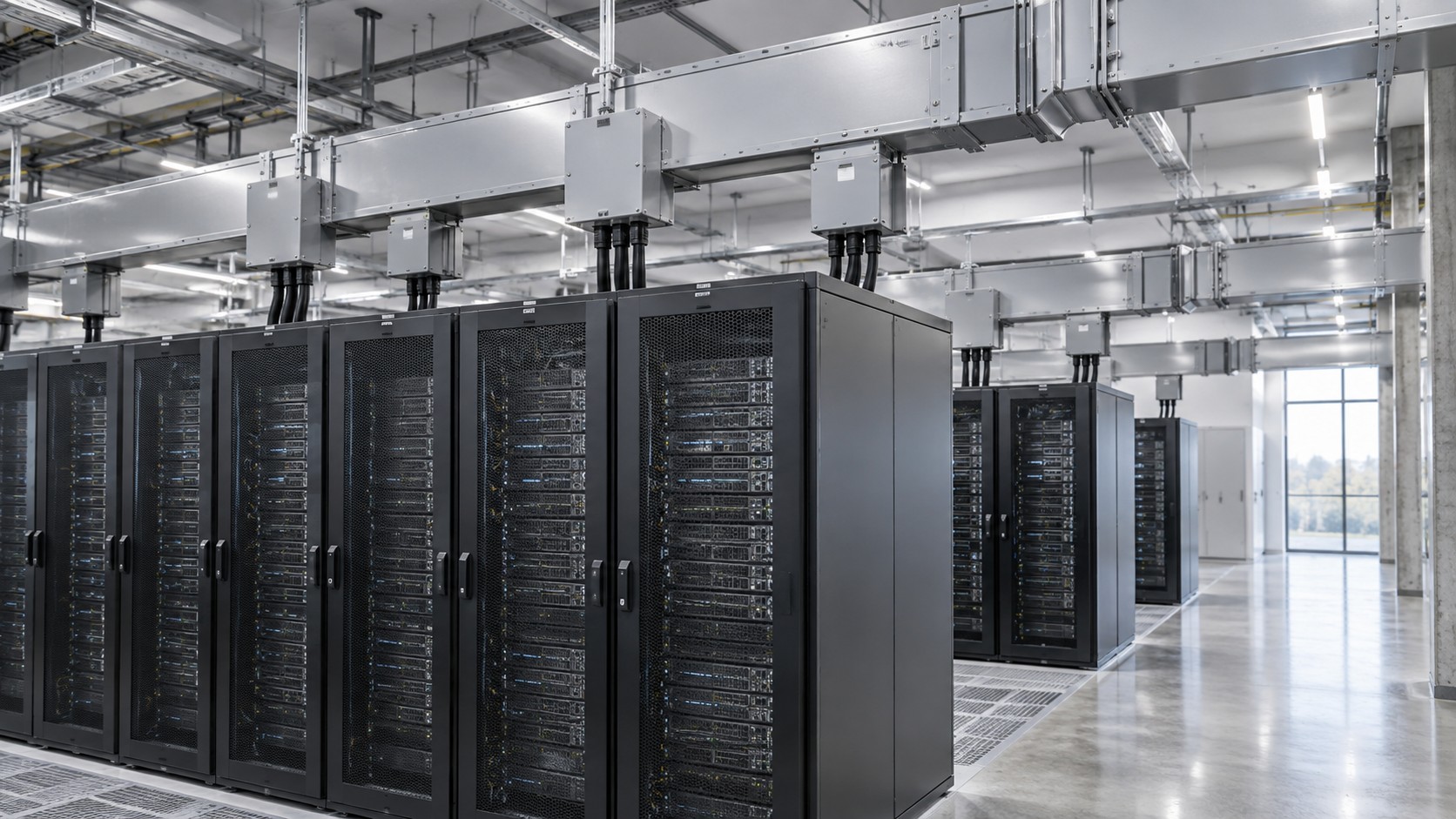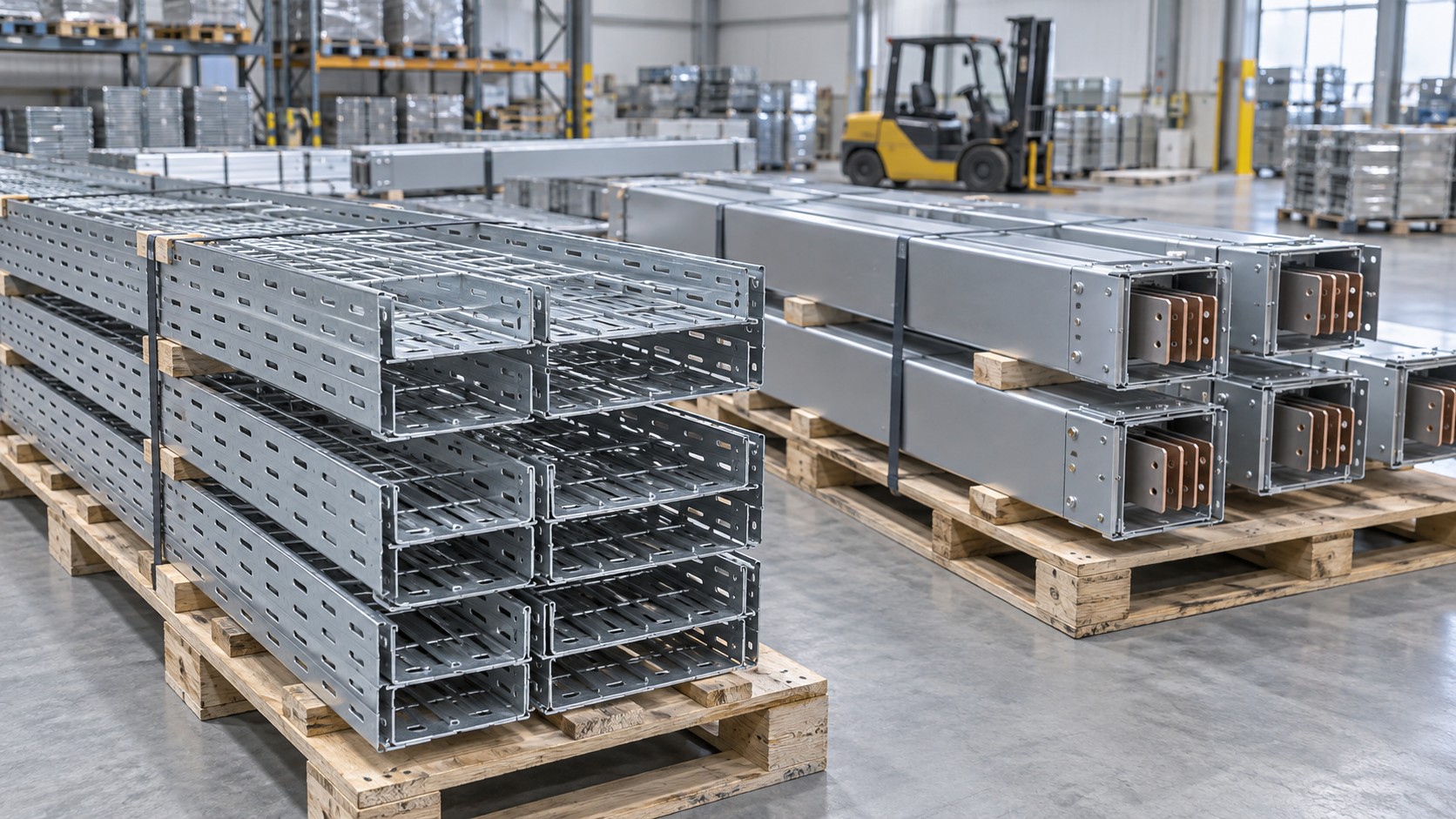
In a modern building the neutral of a busway riser often carries more current than any single phase. LED drivers, IT power supplies and variable-speed drives inject third-harmonic current that adds arithmetically in the neutral, and a system sized on balanced fundamental load will run its neutral bar at 120% of phase current without any breaker noticing. The fix is decided at specification stage: neutral sizing, neutral bar rating and tap-off configuration.
Why harmonic current accumulates in the neutral
In a three-phase four-wire system, the fundamental currents of a balanced load cancel in the neutral. Triplen harmonics — the third, ninth, fifteenth and so on — do not. They are in phase with each other in all three phases, so they add rather than cancel: the neutral carries three times the third-harmonic current of one phase.
For single-phase electronic loads distributed across three phases, the neutral current can approach √3 (about 1.73) times the phase current in the limiting case where the load current is almost entirely third harmonic. That is not a theoretical curiosity. Office floors dominated by LED lighting and desktop IT, data halls with switched-mode power supplies, and any area with a high density of single-phase rectifier loads all produce this pattern.
The relevant reference points are IEC 61000-2-2 and IEC 61000-2-4 for compatibility levels in public and industrial networks, IEEE 519 for harmonic limits at the point of common coupling, and IEC 61000-3-2 for the emission of equipment up to 16 A per phase. Those standards limit what the network should see; they do not size your neutral. That is a separate calculation.
The sizing rule and where it comes from
IEC 60364-5-52 Clause 524 addresses the neutral conductor cross-section, and the principle is straightforward: the neutral must be sized for the current it will actually carry, including harmonic content, not simply matched to the phase conductor. IEC 60364-4-43 adds the protection side — where the neutral cross-section is smaller than the phase conductor, or where third-harmonic content is significant, the neutral needs overcurrent detection, because a reduced neutral can overheat while the phase conductors remain within their rating.
For assemblies, IEC 61439-1 requires the neutral conductor and its bar to be rated for the current they carry, and the temperature-rise verification covers the neutral under the declared loading. This is where a busway differs from a cable: the neutral bar is a physical copper section inside the enclosure, and its temperature contributes to the heat inside that enclosure. A 100% neutral bar running at 1.2 times its nominal current is a genuine thermal problem, not a margin question.
| Neutral option | Bar rating relative to phase | Suitable where | Practical constraints |
|---|---|---|---|
| 100% neutral | Equal to phase | Balanced three-phase motor loads, negligible third-harmonic content | Inadequate above roughly 30% third-harmonic content; needs neutral overcurrent detection if reduced further |
| 150% neutral | 1.5× phase | Mixed office loads with measured THD around 25-35% | Limited product availability; confirm tap-off neutral matches |
| 200% neutral | 2× phase | Data halls, dense IT floors, LED-heavy lighting, areas with high single-phase electronic load | Larger enclosure, higher cost, heavier sections; tap-off units must be ordered with the same neutral |
| Separate neutral per phase | One full neutral per phase | Where phase-to-neutral loads are entirely single-phase and can be kept separate | Four-pole switching complexity; not a standard busway configuration |
Working the numbers
The relationship that matters in practice is simple. If the third-harmonic component of each phase is a fraction k of the fundamental, the neutral current is approximately 3k times the fundamental phase current. So:
- k = 0.20 (20% third harmonic) → neutral at 60% of phase current — a 100% neutral is comfortable.
- k = 0.33 → neutral equals phase current — the crossover point.
- k = 0.40 → neutral at 120% of phase current — a 100% neutral is overloaded at full load.
Example, for illustration only: a riser rated 800 A per phase serving office floors with a measured third-harmonic content of 40% of fundamental. Neutral current is roughly 3 × 0.40 × 800 = 960 A, which is 120% of the phase rating. A 100% neutral bar in an 800 A system would be carrying 960 A. Specify 200% neutral — a 1600 A bar — or reduce the per-floor load. Verify against the actual measured harmonic spectrum and the manufacturer’s thermal data; the figures here demonstrate the method, and the manufacturer’s data and the project specification govern.
Where the harmonic current actually comes from
Three load families dominate in commercial buildings:
- LED lighting with electronic drivers. Cheap drivers without power-factor correction can show third-harmonic content of 30% or more; better drivers stay below 10%. The difference is visible on a power quality analyser in ten minutes and is worth specifying.
- IT and telecom equipment. Switched-mode supplies draw current in short pulses. Dense desktop floors and data halls are the classic 200% neutral application.
- Variable-speed drives and rectifiers. Six-pulse drives produce 5th and 7th predominantly, but the third-harmonic content rises with single-phase front ends and with unbalanced supply.
Measure before you size. A short survey at a representative distribution board gives the spectrum you need, and it is far cheaper than changing a riser after installation.
Consequences beyond the neutral bar
Neutral overheating does not stay inside the neutral. In a busway enclosure, the extra heat raises the internal temperature and therefore the temperature of the phase conductors too, which erodes the derating margin you thought you had. The joints are the most sensitive point, because joint resistance rises with temperature and temperature rises with resistance.
Two further effects are worth checking at design stage. First, if the neutral is switched or protected by a four-pole device, the protection must be rated for the harmonic neutral current, and the device must not nuisance-trip on inrush from LED drivers. Second, where a residual current device is used, harmonic content can produce standing leakage; type A devices may not be appropriate, and type B or a dedicated harmonic filter may be needed depending on the load.
Application case: office floors with LED and IT load
Scenario constraints
A twelve-storey office building uses a single 800 A busway riser with tap-off boxes on each floor. The floors are fitted out with LED lighting on electronic drivers, a dense desktop IT population and a small server room on each third floor. The measured third-harmonic content at a sample floor board is 38% of fundamental, and the shaft ambient reaches 41 °C in summer.
Selection approach
The riser was re-rated for 41 °C ambient before any harmonic allowance, then specified with 200% neutral — a 1600 A neutral bar — and tap-off units ordered with the matching neutral rating. Neutral was left unswitched at the tap-off to avoid a single point of failure on a shared conductor. The 800 A frame was retained rather than upsized, because the phase current itself was within rating; the thermal margin came from the neutral bar section, not from a larger frame. Neutral current monitoring was included at the main tap-off so that the facility team could see the actual loading rather than estimate it.
Common mistakes
- Specifying a 200% neutral riser but standard tap-off boxes with a 100% neutral bar — the bottleneck simply moves to the tap-off.
- Protecting the neutral with a four-pole breaker set to the phase rating, which trips on harmonic neutral current that the bar is designed to carry.
- Sizing on total rms current alone, which hides the harmonic component because the fundamental still dominates the arithmetic.
- Assuming power-factor-corrected LED drivers eliminate third harmonics. They reduce them; they do not remove them.
- Ignoring the shaft temperature, then attributing the resulting joint hotspots to harmonics alone.
Acceptance points
At commissioning: measure neutral current at each tap-off under representative load and record it against the design value; run an infrared scan on the neutral bar and on the joints and compare the neutral-to-phase temperature difference; verify by inspection that no neutral device is being used as a switching point; and retain the harmonic spectrum as a baseline for future comparison. Where measured neutral current exceeds 90% of the bar rating at design load, revisit the load distribution before the building is occupied.
Selection points for a harmonic-rich riser
- Establish the third-harmonic content by measurement, not by assumption.
- Size the neutral bar, not the phase bar, as the limiting element when THD3 is above about 30%.
- Keep the neutral configuration consistent from the riser through every tap-off to the final board.
- Confirm the neutral bar material and plating — tinned copper joints behave differently from bare copper in a warm enclosure.
- Check that the temperature-rise verification covers the neutral at the declared loading, and ask for that specific evidence.
- Decide the neutral switching philosophy before ordering devices.
- Provide neutral current metering at the main tap-off if the load mix is expected to change.
Factory checks that catch neutral problems early
Ask for the neutral bar cross-section on the drawing, in mm², and compare it with the phase bar — a “200% neutral” claim should be visible as a section, not just a note. Check that the neutral bar is continuous across joints with the same contact area as the phases, and that the joint hardware is identical. During routine verification under IEC 61439-6 Clause 11, confirm that the power-frequency dielectric test and the wiring check cover the neutral circuit. On arrival, verify the tap-off units are marked with their neutral rating.
How to judge a supplier on this topic
A supplier who understands harmonic neutral sizing will ask you for the load mix and the measured THD before quoting, and will show the neutral bar section on the general arrangement drawing. Ask what neutral rating their standard tap-off carries, and whether a 200% neutral variant exists as a catalogue item or requires a special. Ask for a temperature-rise test report that identifies the neutral loading. If the answers are vague, the 200% neutral you specified may exist only on the order acknowledgement.
Frequently asked questions
When is 200% neutral actually necessary?
Where the third-harmonic content is high enough that the neutral current approaches or exceeds the phase current — in practice, dense single-phase electronic load such as data halls, IT-heavy office floors and LED-dominated lighting circuits. Measurement, not building type, should decide.
Can I use a 100% neutral and simply derate the busway?
Derating the whole run to protect the neutral wastes phase capacity and does not address the local hot spot at the neutral bar. It is usually more economical to specify the larger neutral.
Does the neutral need overcurrent protection?
IEC 60364-4-43 requires detection of neutral overcurrent where the neutral is reduced relative to the phase conductor, and good practice extends that to harmonic-rich circuits. It does not require the neutral to be switched.
Does a 200% neutral change the enclosure size?
Usually yes, at least in width or bar arrangement, and the mass per metre increases. Confirm the shaft dimensions and the support spacing before the order is released.
What about the fifth and seventh harmonics?
They are negative- and positive-sequence respectively and largely cancel in a balanced system. They matter for transformer loading and for voltage distortion, not primarily for neutral current.
How do I measure harmonic content on an existing installation?
With a power quality analyser capable of per-harmonic recording, at representative load, over a period long enough to capture the daily peak. A single spot reading at light load will understate the problem.
Is aluminium busway affected the same way?
The harmonic behaviour is identical because it depends on the load, not the conductor. Aluminium has different thermal and joint characteristics, so the temperature margin for the same neutral section differs — confirm with the manufacturer.
Specify the neutral correctly the first time
BANGE Electric builds busway systems with 100% and 200% neutral configurations, matched tap-off units and neutral bar sections shown on the arrangement drawing. Tell us the load mix, the measured harmonic spectrum and the shaft ambient, and we will propose the neutral configuration and the derated rating together rather than separately. Requirements may vary by application, market, and applicable standard.