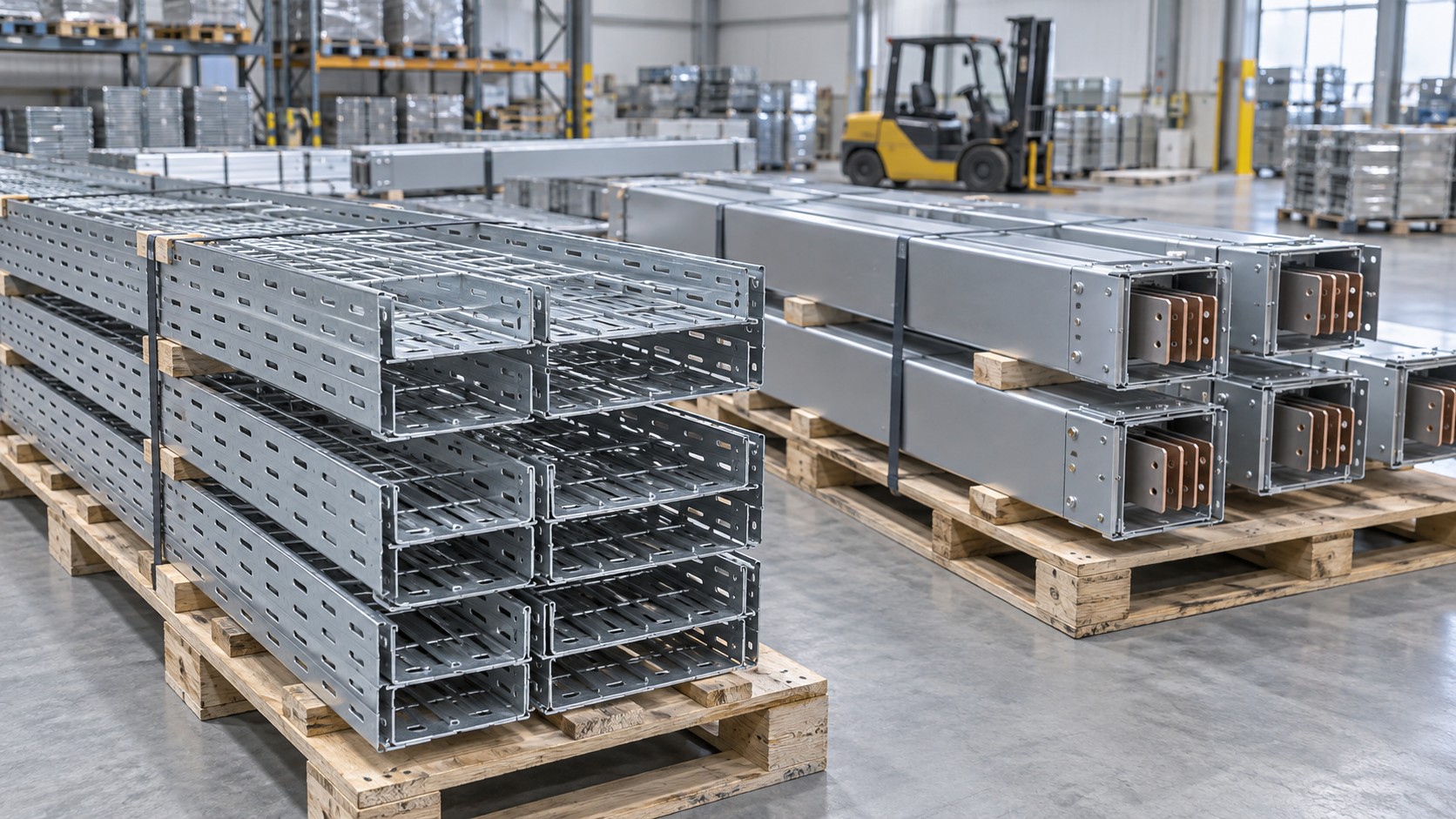
A vertical busway riser in a high-rise is a structural and fire-safety problem as much as an electrical one. The run must carry its own weight across every floor, absorb thermal expansion and building drift, hold its temperature rise inside the verified limit in a shaft that is often the building’s hottest space, and stay sealed at every slab penetration. IEC 61439-6 sets the product rules; the installation detail decides whether they hold for thirty years.
What the standards actually require of a vertical run
Busbar trunking systems are covered by IEC 61439-6, which follows the structure of IEC 61439-1: design verification in Clause 10, routine verification in Clause 11. In China the equivalent series is GB 7251.6; in North America the product standard is UL 857, and installations are governed by NEC Article 368. Three points matter for a riser:
- Mechanical strength is a design-verification item under IEC 61439-1 Clause 10.2. The permitted support spacing is a verified number, not a site decision.
- Temperature rise is verified under Clause 10.10, and the result holds only for the declared ambient, orientation and enclosure. A vertical run in a closed shaft is not the same case as a horizontal run on open tray.
- Short-circuit withstand — Icw and Ipk — must be adequate at the point of installation, not at the transformer terminals. A riser fed from a 2000 kVA transformer at 400 V sees a very different prospective current at floor 3 than at floor 28.
Common practice verifies the riser as one assembly rather than each floor section independently; a riser never verified as a vertical assembly usually shows it first as joint overheating on the upper floors.
Carrying the weight: support strategy floor by floor
Vertical busway is supported at each floor slab, not suspended from the run above. The conventional arrangement is a load-bearing bracket at each floor plus intermediate guides, with the run free to slide at designated points so expansion does not accumulate into the top or bottom termination.
Weight is the first number to establish. A 1000 A copper sandwich system commonly falls in the range of roughly 20 to 35 kg per metre depending on conductor content, housing material and whether an integral earth bar is included. For illustration only: a 90 m riser at 28 kg/m carries about 2.5 t, and each floor bracket in a 3.2 m storey takes roughly 90 kg plus dynamic allowance. Use the manufacturer’s mass per metre before sizing brackets — the figure is an example, not a specification.
| Support type | Function in a vertical run | What to check on site |
|---|---|---|
| Load-bearing floor bracket | Transfers the weight of the section below into the slab | Anchor type and embedment approved for the slab; bracket not resting on blockwork or a non-structural wall |
| Guide bracket | Restrains horizontal movement, allows vertical sliding | Sliding clearance left as specified; no grout or mortar locking the slide |
| Expansion or sliding section | Absorbs thermal growth and inter-floor movement | Installed at the floor level on the drawing, travel indicator visible |
Expansion: the calculation that is usually skipped
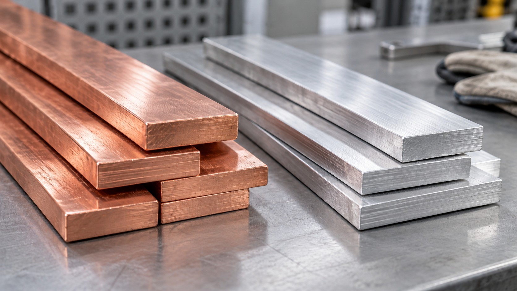
Thermal expansion of the conductor and housing has to go somewhere. For copper, the linear coefficient is about 16.5 × 10⁻⁶ per K; for aluminium about 23 × 10-6 per K. The free expansion is:
ΔL = α × L × ΔT
Worked example, for illustration only: a 60 m copper riser with a conductor temperature swing of 40 K gives 16.5 × 10-6 × 60 000 mm × 40 = 39.6 mm. That is not a tolerance you can absorb in a joint; it needs an expansion section. A 60 m aluminium run under the same conditions would move about 55 mm. Confirm the design temperature swing with the manufacturer — the ambient at installation is rarely the operating ambient.
The practical rules that follow:
- Place expansion sections at floor levels where they can be inspected and where the slab, not the busway, carries the reaction.
- Never place one inside a fire-stop penetration or behind a sealed shaft panel where it cannot be reached.
- Use sliding sections to accommodate building drift rather than forcing the busway to act as a structural tie.
- Leave the specified gap at the top termination. A run installed tight against the upper slab has no travel left and will load the joints instead.
Fire-stopping every slab penetration
In a riser, the floor slab penetration is a compartment boundary, and the busway through it is a service penetration like any other. The relevant test standards are EN 1366-3 for penetration seals, ASTM E814 / UL 1479 in North America and GB 23864 in China. The required performance — typically EI 60 or EI 120, matching the slab — comes from the fire strategy, not the busway datasheet.
Three failures recur often enough to be worth naming:
- Mortar instead of a tested seal. Cement mortar around a busway has no fire test evidence and cracks as the run moves. Use a system with a test report covering the same substrate, penetration size and service type.
- Sealing the gap but not the enclosure. Some designs require an internal barrier or a sealed joint at the penetration. Read the manufacturer’s detail rather than assuming the annular seal is enough.
- Ignoring circuit integrity. Where the riser feeds life-safety loads, the circuit may have to keep working during a fire — a different test regime, IEC 60331-1 and -2 or the PH ratings of BS 8491. A standard EI seal does not deliver that.
Temperature rise and derating in the shaft
IEC 61439-1 Table 6 sets temperature-rise limits — 70 K at terminals for external insulated conductors, and higher limits for bare busbars, with 105 K commonly quoted for bare copper. Those limits are verified at a declared ambient, usually 35 °C. A riser shaft in a glass tower can sit at 40 to 45 °C in summer, and two risers side by side heat each other.
| Shaft ambient at full load | Indicative derating factor | Consequence for a 1600 A nominal run |
|---|---|---|
| 35 °C (reference) | 1.00 | 1600 A |
| 40 °C | 0.94 | approx. 1500 A |
| 45 °C | 0.88 | approx. 1410 A |
| 50 °C | 0.82 | approx. 1310 A |
These factors are indicative and show the order of magnitude; the manufacturer’s derating curves, which also account for enclosure type and grouping, govern. A riser sized at exactly the calculated load with no ambient margin will run hot on the upper floors, where the shaft is warmest and air movement weakest.
Seismic bracing and building movement
Where seismic qualification is required, the usual evidence is vibration testing to IEC 60068-2-6, seismic methods to IEC 60068-3-3, or ICC-ES AC156 in North America; Chinese projects refer to GB 50011. In practice this means bracing at every floor, lateral restraints at the manufacturer’s stated intervals, and flexible connections at transformers and switchboards. The point that gets missed: a shaft wall is not a suitable anchor unless designed as one — bracing into 100 mm blockwork will pull the wall over before it restrains the busway.
Application case: a 28-storey mixed-use tower
Scenario constraints
A tower with retail podium, office floors and residential upper floors needs two risers in a shared shaft of limited plan area. Constraints: shaft ambient measured at 42 °C at the top under summer load, floor-to-floor height 3.3 m, a transfer slab at level 8 that prohibits anchors into the slab soffit, and a fire strategy requiring EI 90 at every floor penetration.
Selection approach
The riser was sized on the derated rating at 45 °C rather than nominal, with the load schedule applied floor by floor so that upper sections could step down at the tap-off points. Sandwich-type construction was chosen for its smaller footprint at high current, with the enclosure rated IP54 for a shaft that is dry but dusty. Expansion sections were placed at levels 8, 16 and 24, each immediately below a floor bracket so the reaction went into the slab. At level 8 the brackets were fixed to a steel secondary frame bolted to the slab edge, because the transfer slab could not be drilled.
Common mistakes on this type of project
- Sizing on nominal rating and discovering at commissioning that the top-floor sections run 15 K hotter than the lower ones.
- Installing expansion sections at mid-storey because that is where the joint fell, leaving them behind a sealed access panel.
- Using the same fire-stop detail at the transfer slab as at a normal slab, where the annular gap is larger.
- Letting the electrical and fire-stop subcontractors each assume the other is sealing the penetration.
Acceptance points
Before handover: verify support spacing against the manufacturer’s installation manual, not the drawing; confirm every expansion section has visible travel remaining; record joint torques taken with a calibrated wrench; confirm each fire-stop has a label, test reference and photographic evidence; and run an infrared scan at full load, comparing joint temperatures against the phase-to-phase spread rather than absolute values alone.
Selection checklist before you order
- Rated current at the declared ambient, after derating for shaft temperature and grouping.
- Icw and Ipk at the actual point of installation, plus the upstream device’s coordination time.
- IP rating matched to the shaft — IP54 indoors, IP65 or better where water ingress is possible.
- Conductor material and neutral configuration, including whether 200% neutral is needed for harmonic-rich loads.
- Fire-stop detail with test evidence, and whether circuit integrity is required.
- Support and expansion drawings for this riser height, and tap-off positions frozen before manufacture.
Factory and site quality checks
At the factory, routine verification under IEC 61439-6 Clause 11 should cover a construction check, a power-frequency dielectric test and a wiring and functional check; ask for the record per shipping section, not a generic certificate. Check plate thickness and coating against the agreed specification — hot-dip galvanising to ISO 1461 and powder coating to the declared microns are both measurable on arrival. On site, confirm sections are stored dry and upright and that joint contact surfaces are untouched.
Evaluating a busway supplier
Ask for type-test reports for the product you are buying, at the same current rating and in the same enclosure — a report for a 630 A air-insulated system does not qualify a 2000 A sandwich system. Ask for the installation manual covering vertical runs, and whether support spacing is stated as a function of current rating. Ask how expansion sections are selected for a given riser height — a calculation, or a rule of thumb.
Frequently asked questions
How often should a vertical busway be supported?
At every floor slab as a minimum, plus intermediate guides where the manual requires them. The exact spacing is a verified value tied to current rating and mass per metre, and must come from the installation manual for that product.
Do I need expansion joints in a heated building?
Yes. The shaft is heated by the busway itself, and the conductor temperature swing between de-energised and full load is typically larger than the ambient swing. Long vertical runs also move with the structure.
Can the busway be used as a structural tie between floors?
No. It must be free to move at the designated sliding points. Restraining it rigidly at every floor transfers inter-storey drift into the joints and the enclosure.
Is IP54 sufficient in a riser shaft?
Usually, for a dry internal shaft. Not where the shaft has open louvres, roof drainage passing through, or condensation risk — those call for IP65 and a condensation management detail.
What fire rating should the penetration seal have?
Whatever the compartment requires, commonly EI 60 or EI 120, evidenced by a test report for the same seal system, substrate and penetration size. The busway rating does not set the seal rating.
How is temperature rise checked after installation?
By infrared thermography at representative load, comparing joints against each other and against the conductor sections, and recording the results so later surveys have a baseline. IEC 61439-1 Clause 10.10 governs type verification, not the site survey.
Does the tap-off box affect the riser rating?
It can. Tap-off units interrupt the conductor run and add a connection; the verified rating applies to the assembly with tap-offs fitted at the specified spacing. Dense tap-off arrangements may require a larger frame size.
Talk to BANGE about your riser design
BANGE Electric manufactures busway systems for vertical risers, plant rooms and long feeders, and issues the support and expansion drawings with the order. Send us the riser height, load schedule and shaft conditions, and we will return a rating and a support layout rather than a catalogue page. Requirements may vary by application, market, and applicable standard.