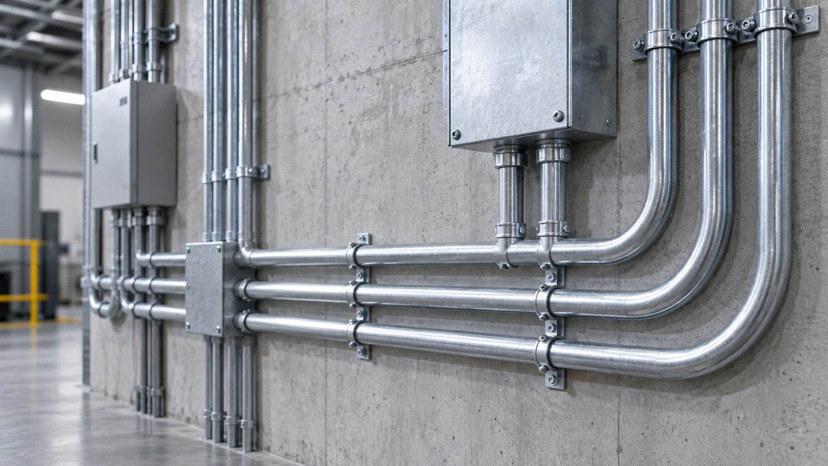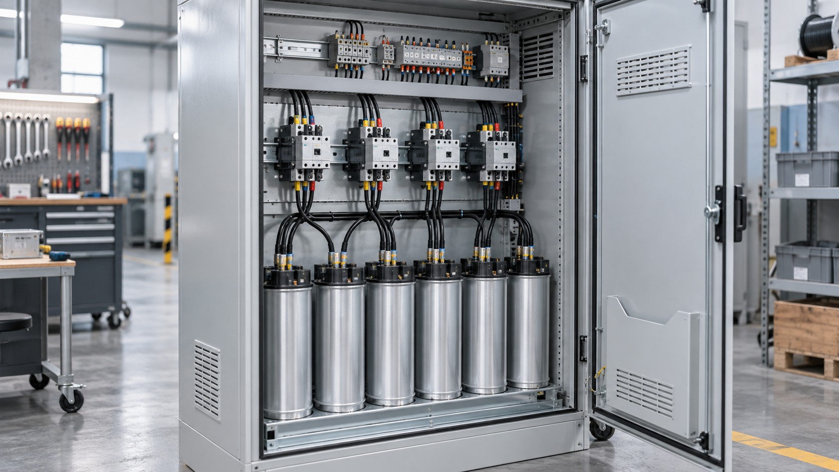
Overhead busbar trunking lets a data hall add or move power without rewiring. The rating is chosen from the row load plus a tap-off density plan, the voltage drop is checked with the resistance and reactance declared under IEC 61439-6, and monitoring is specified at both the feed and the tap-off level so that every rack’s draw is measurable before it becomes a problem.
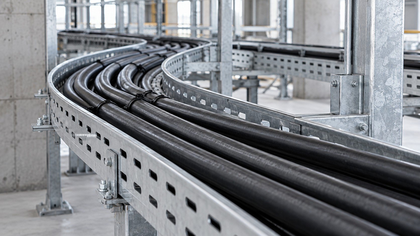
Why data halls moved from cable trays to overhead busway
Row-based distribution has to change as IT load changes. A cable ladder carrying pre-terminated whips locks the hall into a fixed layout; a busway run with plug-in openings turns power into a repositionable service. Moves, adds and changes happen at the tap-off box instead of at the panelboard, which keeps spare capacity at the row rather than stranding it in a distant room.
The electrical case rests on four measurable things: the ampere rating of the run, how many tap-offs the run can physically and thermally accept, the voltage drop from the source to the last tap-off, and the monitoring resolution available to the operations team.
Ratings and the standards that apply
Busbar trunking is covered by IEC 61439-6 with IEC 61439-1 providing the general rules; in North America, busways fall under UL 857 and NEC Article 368. Typical overhead data-hall runs are offered in steps such as 250 A, 400 A, 630 A, 800 A, 1 000 A and 1 250 A, with larger ratings used for the main feeder between the transformer and the hall.
Three ratings must be read together rather than in isolation:
- Rated current (In) — the continuous current the run carries under the manufacturer’s reference conditions. Confirm whether the published figure assumes the standard ambient (mean not above +35 °C over 24 h, peak not above +40 °C per IEC 61439-1) or a data-hall specific condition.
- Rated short-time withstand current (Icw) and peak withstand current (Ipk) — the fault rating of the assembly. IEC 61439-1 relates them with a factor of 1.5 up to 5 kA, 1.7 above 5 kA to 10 kA, 2.0 above 10 kA to 20 kA, 2.1 above 20 kA to 50 kA and 2.2 above 50 kA. Data hall feeders are commonly specified in the tens of kiloamperes for 1 s.
- Degree of protection — IEC 60529 IP codes, with a minimum of IP2X for protection against direct contact under IEC 61439-1. Unused plug-in openings must be covered so that this protection is maintained.
Tap-off density: the number that decides your layout
Tap-off units are the devices that convert the busway into usable outlets. Their ratings are typically in the 16 A to 63 A range for rack-level supplies, with larger units up to 125 A or 250 A for high-density cabinets. Two limits apply:
- Physical spacing — plug-in openings are offered at regular intervals; the manufacturer states the minimum centre-to-centre distance between tap-off units, which sets how many racks a given run can serve.
- Thermal and electrical limit — the temperature-rise verification under IEC 61439-6 was performed with a specific number and arrangement of tap-offs. Exceeding that number without the manufacturer’s confirmation invalidates the verification.
Plan tap-off density together with the rack layout. A run serving 20 cabinets at 32 A each is a different product decision from a run serving 8 cabinets at 63 A each, even though the arithmetic looks similar.
Voltage drop: use declared values, not guesswork
IEC 61439-6 requires the manufacturer to declare resistance, reactance and voltage drop characteristics, which makes the calculation straightforward. The three-phase drop over a length L is:
ΔU = √3 × I × (R cos φ + X sin φ) × L
where R and X are the manufacturer’s declared resistance and reactance per metre. Worked example, illustrative only: a 60 m run carrying 400 A with declared values of R = 0.05 mΩ/m and X = 0.03 mΩ/m at a power factor of 0.95 (cos φ = 0.95, sin φ = 0.312):
ΔU = 1.732 × 400 × (0.00005 × 0.95 + 0.00003 × 0.312) × 60 ≈ 1.732 × 400 × 0.0000569 × 60 ≈ 2.36 V
On a 400 V system that is roughly 0.6 %. Many projects budget a total drop of around 5 % from transformer to the furthest outlet, so the busway portion is usually a small slice — but it must be extracted from the declared data, not estimated. Always confirm with the manufacturer’s tables and the project specification.
Neutral and harmonic considerations
Racks are overwhelmingly single-phase electronic loads. Switch-mode power supplies generate third-order and other triplen harmonics that do not cancel in the neutral, so the neutral conductor can carry a current comparable to or greater than the phase currents. Busway is therefore offered with neutral options commonly expressed as 100 % or 200 % of the phase conductor rating. Where the load is dominated by IT equipment, specify the neutral deliberately rather than by default, and where a 200 % neutral is used, check its effect on the assembly’s short-circuit verification.
Monitoring: what to measure and where
Metering at the feed is the minimum; per-tap-off metering is what actually supports capacity management. Useful instrumentation per IEC 61557-12 includes current and voltage per phase, power and energy, and increasingly temperature sensing at the joints and at plug-in contacts. Two practical points:
- Accuracy class matters. If the measurement is used for capacity charging or for enforcing a rack power cap, specify the accuracy class required rather than accepting “metering included”.
- Joint temperature is the single most useful predictive measurement on a busway, because a rising joint resistance shows up as heat long before it becomes a fault. The scan must have a baseline: record temperatures at commissioning under a known load.
Busway vs cable tray for the same row
| Criterion | Overhead busway | Cable ladder or tray with whips |
|---|---|---|
| Adding a rack circuit | Plug in a tap-off unit at the nearest opening | Pull and terminate a new cable from the panelboard |
| Rating headroom | Run sized once; capacity added by tap-offs | Capacity tied to the installed cable and the panelboard spare ways |
| Declared electrical data | R, X and voltage drop per metre per IEC 61439-6 | Cable resistance from the cable standard; assembly drop not declared as a system |
| Fault rating | Icw and Ipk declared for the assembly, with verified support spacing | Depends on cable, protection and support of the tray |
| Metering granularity | Per tap-off metering readily available | Typically at the panelboard, unless branch metering is added |
| Applicable standards | IEC 61439-6, UL 857, NEC 368 | IEC 61537 / NEMA VE 1 / NEC 392 for the tray |
Application Scenario: Row-Based Distribution in a High-Density Data Hall
Scenario constraints
A hall is fitted with racks whose average draw is well above legacy levels, meaning each cabinet may require a 32 A or 63 A single-phase supply rather than the 16 A used a decade ago. The ceiling void is shared with containment, cooling pipework and fibre. The operator requires A and B power paths to dual-corded equipment, and requires per-rack current visibility for capacity reporting.
Selection approach
Size each run from the sum of the connected tap-off ratings multiplied by an agreed diversity factor, not from the arithmetic sum, and then check the result against the hall’s stated redundancy scheme. For a dual-path design, the two runs must be physically separated so that a single event cannot affect both. Choose tap-off units with the protective device rating matching the rack’s inlet requirement, and leave a defined number of unused openings for future cabinets. Confirm the number of tap-offs considered in the temperature-rise verification, and require that the monitoring system reports per-tap-off current into the DCIM or BMS.
Common mistakes
- Sizing the run from the sum of all tap-off ratings without applying diversity, then discovering the run is oversized and the tap-off spacing is wrong.
- Mixing tap-off ratings across a run without checking how the manufacturer verified the mixed arrangement.
- Routing both A and B paths in the same void without separation, so a single leak or impact affects both.
- Specifying “monitored busway” without stating accuracy class, sampling interval or which values are reported.
- Leaving plug-in openings uncovered, which removes the IP2X protection required by IEC 61439-1.
Acceptance checkpoints
- Type-test report covers the shipped rating, pole count, neutral option and IP code.
- Tap-off count and spacing match the arrangement covered by the temperature-rise verification.
- Support spacing on site matches the spacing used in the short-circuit test.
- Voltage drop calculated from declared R and X per metre and compared with the project limit.
- Baseline thermal scan recorded at commissioning under a documented load.
- A and B paths verified by selective energisation and recorded on the as-built drawings.
Procurement checklist
- Rated current, Icw with duration and Ipk, IP and IK codes, neutral option.
- Tap-off unit ratings, minimum spacing, interlocking and insertion under load policy.
- Declared R, X and voltage drop per metre at rated current (IEC 61439-6).
- Monitoring options, accuracy class and integration protocol.
- Fire performance of insulating parts and cable accessories: IEC 60332 flame propagation, IEC 61034 smoke density, IEC 60754 halogen content, or the Euroclass route under EN 50575 / EN 13501-6 where the project is in Europe.
- Torque tables and joint preparation instructions for installation teams.
Supplier evaluation questions
Ask which ambient temperature the published current ratings assume, how many tap-offs were in the temperature-rise test, what support spacing the Icw figure was verified at, and whether the monitoring system can report per-tap-off values into your existing platform. Suppliers who answer with numbers and test report references are worth shortlisting; suppliers who answer with adjectives are not. Product options are listed under busway systems.
Frequently asked questions
1. Which standard applies to data centre busway?
IEC 61439-6 together with IEC 61439-1 internationally; UL 857 and NEC Article 368 in North America. Confirm which regime your project follows before writing the specification.
2. How many tap-off units can one run accept?
The limiting factors are the manufacturer’s minimum spacing and the number of tap-offs covered by the temperature-rise verification. Both must be confirmed in writing for your specific arrangement.
3. What neutral size should I specify for IT loads?
Systems are offered with neutral at 100 % or 200 % of the phase rating. Where single-phase switch-mode loads dominate, the larger option is commonly considered; confirm against harmonic measurements or the manufacturer’s guidance.
4. Is busway cheaper than cable?
Material and labour balance differently by project. Compare on the full cost — including moves, adds and changes, and the cost of stranded capacity — rather than on metre rates alone.
5. Can tap-off units be plugged in while the run is live?
It depends on the design and on the interlock. Some units are designed for insertion under load, others require the downstream load to be off. Follow the manufacturer’s instruction and the local electrical safety rules.
6. What degree of protection is needed?
IEC 61439-1 requires protection against direct contact, typically verified as IP2X, and enclosures are commonly offered at higher IP ratings. Unused openings must be covered to maintain the rating.
7. How is voltage drop verified?
From the resistance and reactance per metre declared under IEC 61439-6, applied to the actual length and load, then compared with the project’s voltage drop budget.
Designing row-based power?
BANGE Electric supplies busbar trunking systems with tap-off options and monitoring interfaces suitable for data hall distribution. Contact our team with your row layout and load plan. Requirements may vary by application, market, and applicable standard.