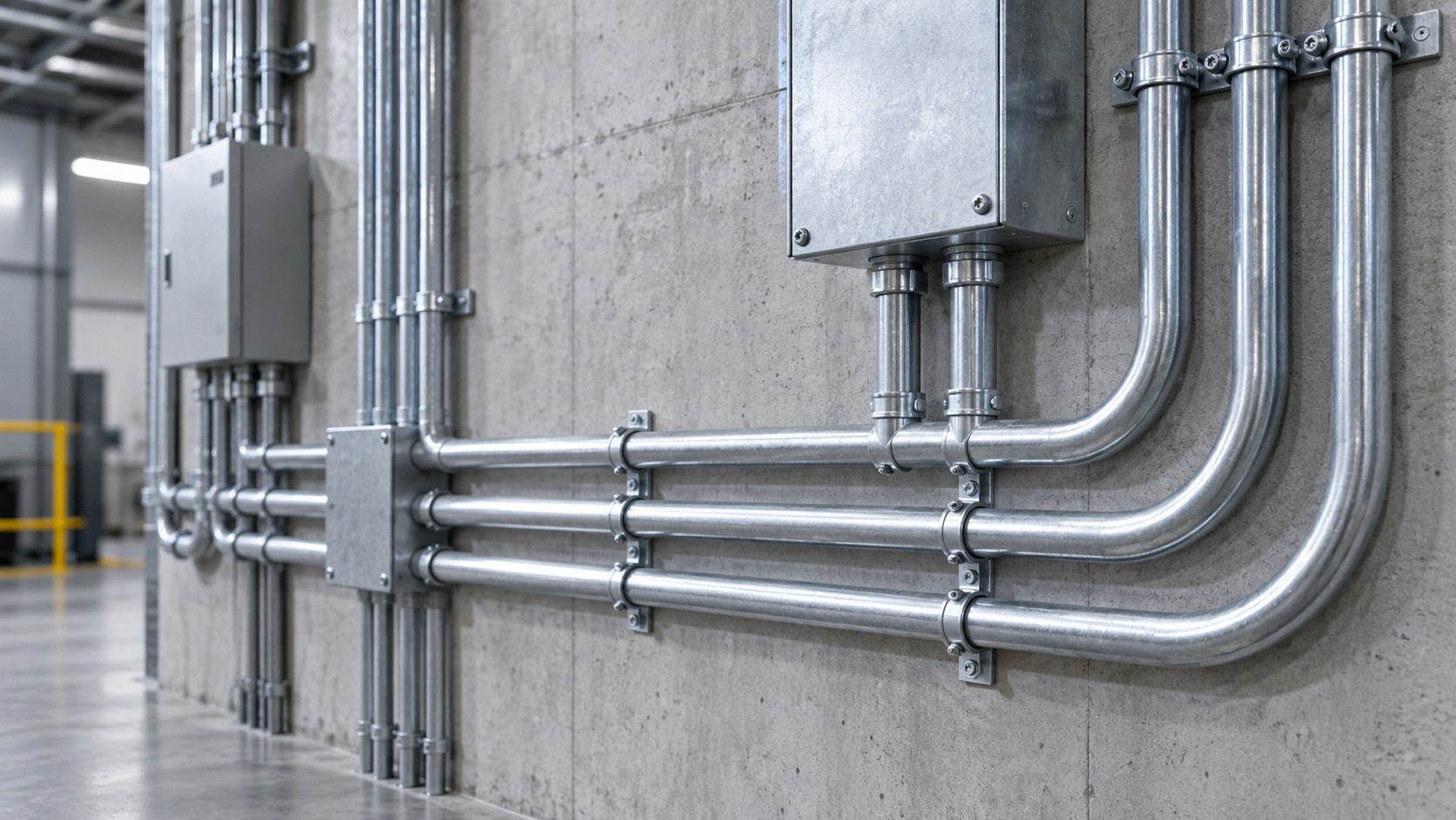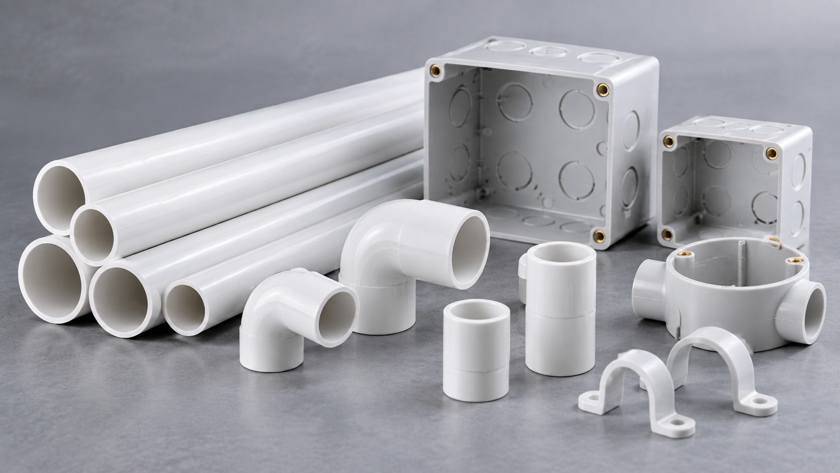
A distribution board on the DC side of a photovoltaic array or a battery system is not a standard AC board painted a different colour. It has to interrupt DC arcs, withstand a DC system voltage of 1 000 V or 1 500 V, carry surge currents, and in the case of batteries, cope with a prospective fault current that does not behave like a transformer’s. The enclosure, the switching devices and the surge protection all have to be DC-rated.
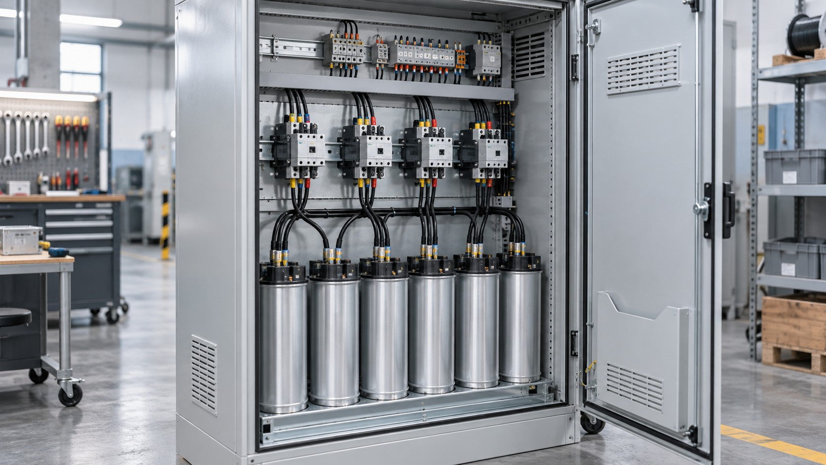
What changes on the DC side
Alternating current crosses zero every half cycle, which helps extinguish an arc when a contact opens. Direct current does not, so a switching device or a circuit breaker rated only for AC may fail to interrupt a DC fault. This single fact drives most of the design differences:
- Devices must carry a DC voltage rating and a DC utilisation category — for switch-disconnectors under IEC 60947-3, categories such as DC-21A or DC-22A.
- Breaking capacity must be stated for DC, and at the actual system voltage. Many DC-rated moulded-case breakers require two or more poles in series to achieve their published DC rating; the wiring diagram in the manufacturer’s data is part of the rating.
- Polarity matters. Fuses and single-pole devices must be placed and wired so that the arc is interrupted in the intended direction.
Standards that apply
Both the assembly and the application have their own standards, and a compliant board has to satisfy both:
- Assembly — IEC 61439-1 general rules, with IEC 61439-2 for power switchgear and controlgear assemblies or IEC 61439-3 for distribution boards, depending on the rating and who operates it. For empty enclosures, IEC 62208.
- PV application — IEC 60364-7-712 for PV power supply systems and IEC 62548 for PV array design requirements; inverter safety under IEC 62109-1 and IEC 62109-2.
- Storage application — the IEC 62933 series for electrical energy storage systems; in North America UL 9540 and UL 9540A for energy storage equipment, NFPA 855 for installation, and NEC Article 706 with Article 480 for batteries.
- Interconnection — NEC Article 690 for solar photovoltaic systems and NEC Article 705 for interconnected electric power production sources, including the rapid shutdown requirements of NEC 690.12: within 30 seconds of initiation, conductors outside the array boundary must be limited to not more than 30 V and 240 VA.
- Surge protection — IEC 61643-11 for AC low-voltage SPDs and IEC 61643-31 for SPDs on the PV DC side.
- DC arc faults — UL 1699B covers photovoltaic DC arc-fault circuit protection; DC arc faults in PV arrays are a recognised fire cause and do not reliably trip conventional overcurrent devices.
Surge protection on the DC side: sizing Ucpv correctly
An SPD installed on the PV DC side is selected on its maximum continuous operating voltage for PV applications, Ucpv. The array’s open-circuit voltage rises as cell temperature falls, so the selection must use the cold-temperature Voc, not the value at standard test conditions.
Worked example, illustrative only: a string with a manufacturer’s Voc of 1 000 V at 25 °C and a temperature coefficient of Voc of −0.30 %/K, at a site minimum cell temperature of −10 °C:
Correction factor = 1 + 0.0030 × (25 − (−10)) = 1 + 0.0030 × 35 = 1.105
Corrected Voc ≈ 1 000 × 1.105 = 1 105 V
The SPD must have a Ucpv above that value, with margin. Selection also considers the discharge current: Type 2 SPDs are commonly specified with In of 20 kA and Imax of 40 kA on an 8/20 µs waveform, while Type 1 SPDs are tested with a 10/350 µs impulse and carry an Iimp value such as 12.5 kA. Confirm all values against the manufacturer’s data and the project specification — this example is for method only.
Residual current protection for inverter circuits
Inverters contain a DC link and can inject smooth DC residual current into the AC side, which can blind a conventional Type A RCD. The two recognised routes are a Type B residual current device per IEC 62423, or a Type A device combined with a residual direct current detecting device (RDC-DD) per IEC 62955, which is required to operate at smooth DC residual currents above 6 mA. Specify which route the design uses rather than leaving it to the installer.
Enclosure and environmental requirements
Outdoor PV and battery enclosures face UV, temperature cycling and rain. Practical parameters to state in the specification:
- Degree of protection — IP code per IEC 60529, commonly IP65 for outdoor boards, with mechanical impact resistance per IEC 62262 (IK08 = 5 J, IK10 = 20 J).
- Material and finish — steel with a suitable coating system, stainless steel for coastal or aggressive atmospheres, or a UV-stabilised non-metallic enclosure; weathering performance is verified to standards such as ISO 4892-2.
- Cable entries — glands from the bottom where possible to keep water out, with the IP rating of the gland matched to the enclosure.
- Internal environment — DC fuses and breakers dissipate heat, so the board’s temperature rise must be verified; where humidity is a risk, a drained breather or a hygrostat-controlled anti-condensation heater is used while maintaining the declared IP rating.
- Operating temperature range — state it, and apply the manufacturer’s derating above the declared ambient.
AC side vs DC side requirements
| Criterion | DC side (array / battery) | AC side (inverter output / interconnection) |
|---|---|---|
| Typical system voltage | 1 000 V or 1 500 V DC | 230/400 V or 277/480 V AC, 50 or 60 Hz |
| Switching device standard | IEC 60947-3 with DC categories such as DC-21A / DC-22A | IEC 60947-2, IEC 60898-1 or UL 489 as applicable |
| Interrupting difficulty | No current zero crossing; polarity and series-pole arrangements matter | Current zero crossing assists interruption |
| Surge protection | IEC 61643-31, selected on Ucpv | IEC 61643-11, selected on Uc |
| Residual current | DC arc-fault protection, e.g. UL 1699B | Type B per IEC 62423, or Type A plus RDC-DD per IEC 62955 |
| Fault source | Battery fault current with a short time constant; array current limited by irradiance | Grid and inverter contribution |
| Safety requirements | Rapid shutdown, e.g. NEC 690.12: 30 V and 240 VA within 30 s | Islanding protection and interconnection rules |
Application Scenario: Rooftop PV Coupled with a Battery System
Scenario constraints
A commercial rooftop array is coupled with a battery energy storage system feeding the building’s main distribution. The DC boards sit outdoors next to the inverter and battery container, the array voltage approaches the 1 500 V DC class, the site has a wide temperature range, and the local authority requires a visible, lockable isolation point for emergency responders.
Selection approach
Start from the DC system voltage and the corrected cold-temperature Voc, then select the DC switch-disconnector and any DC breakers with matching DC ratings and the manufacturer’s required pole arrangement. Size the SPD on Ucpv with margin above the corrected Voc, and coordinate it with the AC-side SPD. Specify residual current protection for the inverter output using either Type B devices or the RDC-DD route, and confirm that the battery’s prospective short-circuit current is below the DC breaking capacity of every device in the fault path. Finally, provide a lockable, clearly labelled isolator in a location agreed with the fire service, and confirm the rapid shutdown arrangement meets the applicable code.
Common mistakes
- Using AC-rated breakers on DC circuits because the ampere rating looks adequate.
- Sizing the SPD from the Voc at 25 °C and ignoring the cold-temperature correction.
- Ignoring the manufacturer’s series-pole wiring diagram, which is part of the DC breaking rating.
- Fitting a standard Type A RCD on an inverter output without addressing smooth DC residual current.
- Mounting cable glands on the top or side of an IP65 enclosure, creating a water ingress path.
- Omitting DC arc-fault protection on PV circuits where the applicable code requires it.
Acceptance checkpoints
- Every DC device carries a DC voltage rating and utilisation category on its marking.
- Breaking capacity at the system DC voltage exceeds the calculated prospective fault current.
- SPD Ucpv exceeds the corrected cold-temperature Voc, with margin; SPD status indication is visible.
- Enclosure IP and IK ratings confirmed, with glands rated to match.
- Isolation point lockable and labelled; rapid shutdown function tested and timed.
- Torque records for all DC terminations, using the device manufacturer’s values.
- Insulation resistance and polarity checks recorded before energisation.
Procurement checklist
- DC system voltage, corrected Voc, and array or battery short-circuit current.
- Device DC ratings, utilisation categories and required pole arrangements.
- SPD type, Ucpv, In / Imax or Iimp, and status indication.
- Enclosure material, IP and IK codes, operating temperature range and derating.
- Cable gland sizes and quantities, entry position.
- Labelling and documentation language requirements.
- Applicable regional code: IEC regime, NEC 690 / 705 / 706, UL 1741, UL 9540 as relevant.
Supplier evaluation questions
Ask which DC standards the devices are certified to, whether the assembly has been verified under IEC 61439-1 with IEC 61439-2 or -3, and what the declared breaking capacity is at your actual DC voltage. Ask for the series-pole wiring diagram and the enclosure’s IP and IK test references. Product scope is shown under distribution boxes.
Frequently asked questions
1. Can I use an AC circuit breaker on a DC circuit?
Not unless it carries a DC rating at your system voltage. DC arcs do not have a current zero crossing, so AC-only devices may fail to interrupt.
2. What standards cover PV DC surge protection?
IEC 61643-31 covers SPDs for photovoltaic installations; IEC 61643-11 covers the AC side.
3. Why does cold temperature matter for SPD selection?
Module open-circuit voltage rises as temperature falls, so the SPD’s Ucpv must exceed the corrected Voc at the site’s lowest expected cell temperature.
4. What residual current protection suits an inverter output?
Type B per IEC 62423, or Type A combined with an RDC-DD per IEC 62955 which operates above 6 mA of smooth DC residual current.
5. What is rapid shutdown?
Under NEC 690.12, conductors outside the array boundary must be reduced to not more than 30 V and 240 VA within 30 seconds of initiation. Confirm the requirement in your jurisdiction.
6. What IP and IK ratings are typical outdoors?
IP65 per IEC 60529 is common, with IK08 (5 J) or IK10 (20 J) per IEC 62262 where impact resistance is specified.
7. Do batteries change the short-circuit calculation?
Yes. Battery fault current has a very short time constant and can be high; use the battery manufacturer’s data and DC-rated breaking capacities for every device in the path.
Designing PV or storage distribution?
BANGE Electric supplies enclosures and distribution boards for PV and energy storage applications. Contact our team with your system voltage, fault level and site conditions. Requirements may vary by application, market, and applicable standard.