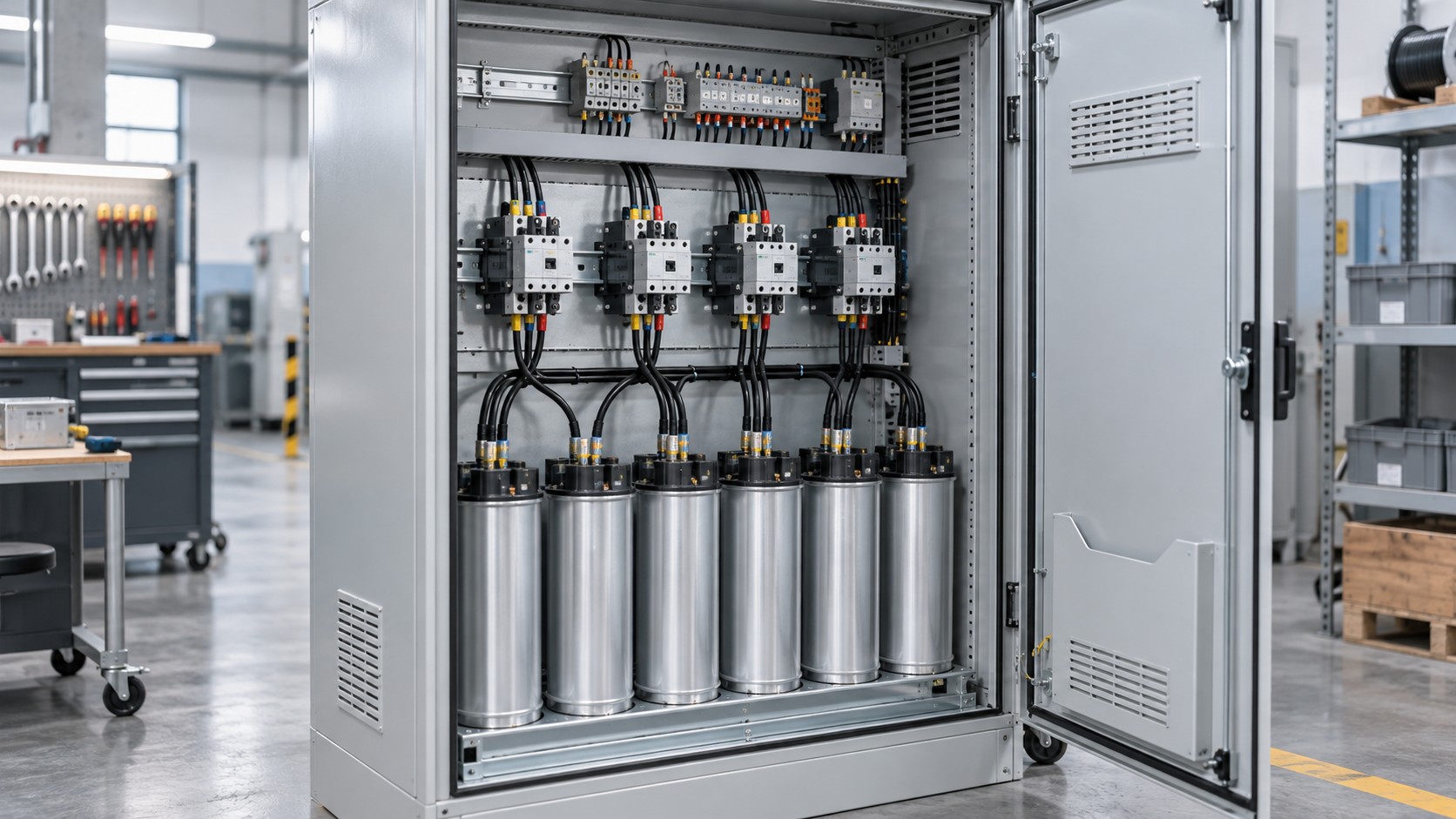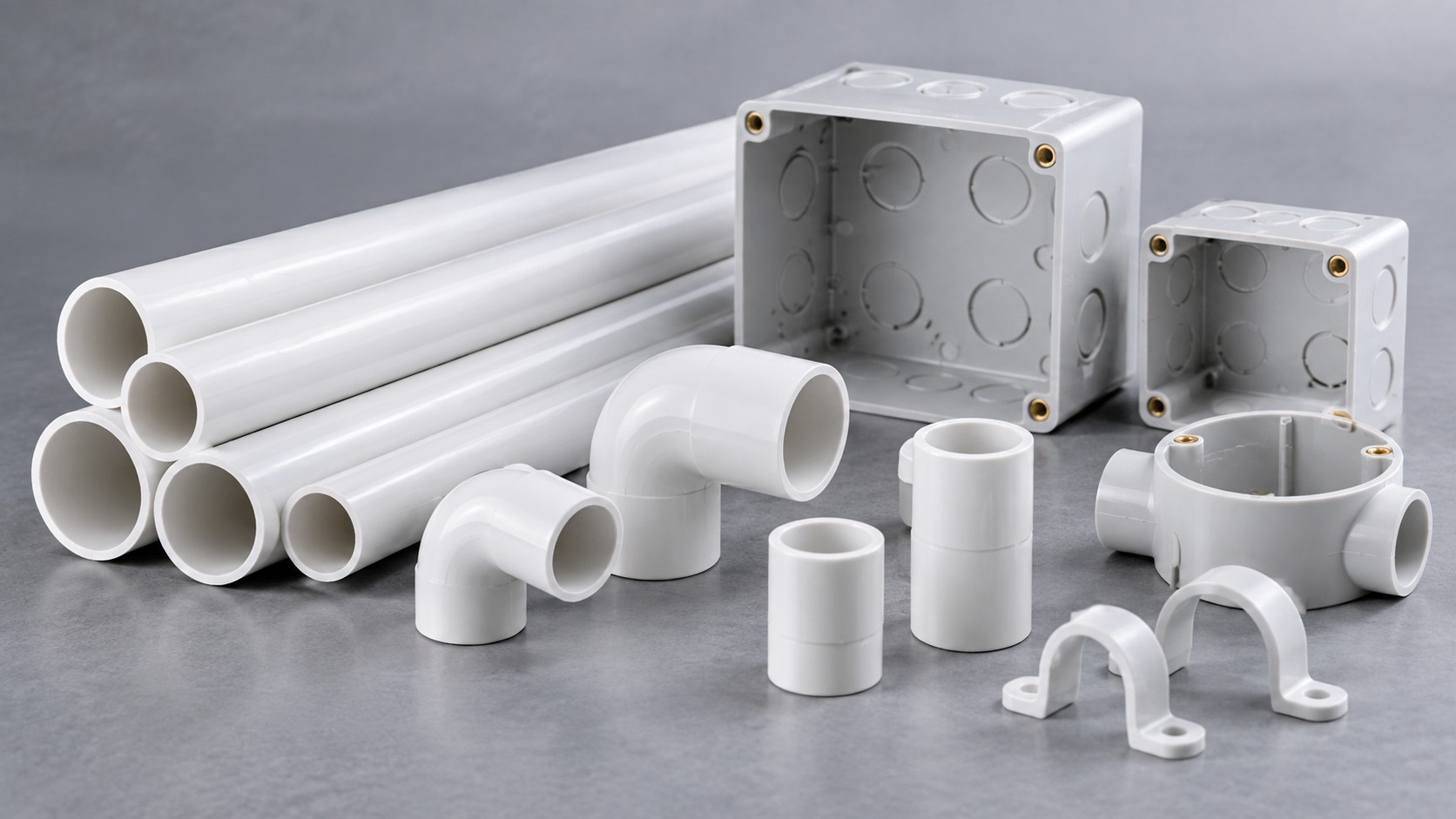
A distribution board that meets its ratings on paper can still fail in service because of how it is laid out and wired: conductors bent tighter than the minimum radius, two cables in a terminal declared for one, devices packed so tightly that the temperature rise exceeds the verified limit, or an unlabelled neutral bar. IEC 61439-3 and IEC 61439-1 set out what has to be verified, and the practical rules below translate that into things you can check on the bench.
Which standard applies to your board
IEC 61439-3 covers distribution boards, distinguishing assemblies intended for use by ordinary persons (DBU) from those intended for instructed persons (DBO). It applies within defined limits of voltage and incoming rated current, so confirm the scope limits in the current edition before assuming a board falls inside it. IEC 61439-1 supplies the general rules and the verification methods; IEC 61439-2 applies to power switchgear and controlgear assemblies and is the part that defines the commonly referenced forms of internal separation.
Where ordinary persons can open the door, protection against direct contact is a design requirement — commonly verified to at least IP2X, and expressed as IP2XC when the ring probe test is included. Internal barriers, shrouds and terminal covers are what deliver that rating once the door is open.
Clearances and creepage: the numbers behind the spacing
IEC 61439-1 Clause 10.4 requires clearances and creepage distances to be verified against the assembly’s rated impulse withstand voltage (Uimp), the pollution degree and the insulating material group. Design verification is normally performed by an impulse withstand test rather than by measurement alone, but the design values still govern how tightly conductors and devices may be packed.
Minimum clearances under inhomogeneous field conditions are typically of the following order:
| Rated impulse withstand voltage Uimp | Typical minimum clearance | Practical implication for layout |
|---|---|---|
| 2.5 kV | 1.5 mm | Tight layouts possible; still requires separation of bare live parts from the enclosure |
| 4 kV | 3.0 mm | Typical for many commercial distribution boards |
| 6 kV | 5.5 mm | Spacing between busbar phases and between phases and earth becomes a visible design constraint |
| 8 kV | 8.0 mm | Usually associated with equipment nearer the origin of the installation |
Creepage depends additionally on the material group of the insulating parts and on the pollution degree — indoor commercial boards are commonly designed for pollution degree 2, while industrial or unprotected outdoor locations are treated as pollution degree 3. Confirm the declared values in the manufacturer’s verification record; the figures above are indicative of the method, not a substitute for it.
Forms of internal separation
Internal separation describes how far the board isolates its busbars, its functional units and their external terminals from each other. The conventional scheme runs from Form 1 to Form 4:
| Form | Busbars separated from functional units | Functional units separated from each other | Terminals for external conductors separated from functional units | Typical use |
|---|---|---|---|---|
| Form 1 | No | No | No | Small boards where maintenance under voltage is not envisaged |
| Form 2 | Yes | No | No | Protects the busbar zone from work on devices |
| Form 3 (3a / 3b) | Yes | Yes | 3b: yes; 3a: no | Allows work on one outgoing way with the rest energised |
| Form 4 (4a / 4b) | Yes | Yes | Yes (4b: in a separate compartment or external) | Allows cable termination work while the rest of the board stays live |
Specifying a form without specifying how the board will be maintained is wasted money. The right question is: what work must be possible with the board energised? The answer sets the form.
Rated diversity factor: the most misunderstood rating on the plate
The rated diversity factor (RDF) is the per-unit value of the incoming circuit’s rated current that the assembly is verified to carry simultaneously across its outgoing circuits. It is declared by the manufacturer and verified as part of the temperature-rise verification under IEC 61439-1 Clause 10.10. Loading a board as though every outgoing way runs at its full rating when the declared RDF is lower is a genuine overheating risk, not a paperwork issue. Read the RDF off the rating plate and apply it to the load schedule.
Wiring practice inside the enclosure
- One conductor per terminal unless the terminal is declared and marked for more. Terminal blocks are covered by IEC 60947-7-1 and IEC 60947-7-2, and clamping units by IEC 60999-1.
- Minimum bending radius follows the cable construction rules of IEC 60364-5-52, usually expressed as a multiple of the cable’s overall diameter. A conductor forced into a corner tighter than its permitted radius risks insulation damage that will not show up in a continuity test.
- Colour identification per IEC 60445: L1 brown, L2 black, L3 grey, neutral light blue, protective conductor green-and-yellow. Mixing colour systems on one site is a recurring source of commissioning errors.
- Wiring duct fill — good practice keeps the duct fill to about half of the available cross-section so that heat can escape and additions remain possible. Confirm any project-specific limit.
- Termination torque — use the device manufacturer’s values, applied with a calibrated tool. Typical values used in practice are of this order, for illustration only: M4 about 1.2 N·m, M5 about 2.0 N·m, M6 about 3.0-4.0 N·m, M8 about 8-10 N·m, M10 about 15-20 N·m. Always defer to the manufacturer’s table.
- Grouped device derating — protective devices mounted side by side heat each other. Manufacturers publish grouping factors, commonly in the 0.8-0.9 range depending on the number of devices and the ambient. Apply them; do not assume the nominal rating holds in a fully populated enclosure.
- Spare capacity — leave spare ways, spare terminal capacity and physical room. A board delivered full has no future.
Application Scenario: Floor Distribution Board in a Commercial Building
Scenario constraints
A floor board serves lighting circuits, socket-outlet circuits and small power for HVAC units, installed in a cupboard accessible to cleaning and maintenance staff. The loads are unbalanced across phases, the board will be modified as partitions move, and the building operator wants individual circuit energy monitoring.
Selection approach
Choose the incoming rating from the diversified load schedule, then check the outgoing ways against the declared RDF. Because staff may open the door, specify internal barriers and terminal shrouds that maintain the required protection against direct contact. Group the circuits by function so that future changes are contained, balance the single-phase circuits across the three phases at the design stage rather than on site, and provide spare ways plus physical space for monitoring current transformers if sub-metering is required.
Common mistakes
- Loading the board to the sum of the outgoing device ratings, ignoring the declared RDF.
- Packing devices without applying the manufacturer’s grouping derating factor.
- Two conductors in a terminal not declared for it — a common cause of loosened connections and heat.
- Mixing conductor colour codes between an existing installation and an extension.
- No circuit schedule, or a schedule that no longer matches the board after modifications.
- Cable entries cut on site without maintaining the enclosure’s IP rating.
Acceptance checkpoints
- Rating plate present, with RDF, Uimp, rated current and the reference to the standard.
- Declared form of separation matches the specification.
- Torque records for busbar and device terminations, with the wrench calibration date.
- Insulation resistance and polarity checks recorded; protective conductor continuity verified.
- Every circuit labelled and cross-referenced to an updated schedule.
- Thermal scan at commissioning under load, retained as a baseline.
Quality inspection points before delivery
Inspect for: conductor bending radii, absence of stranded conductor strands outside the terminal, correct ferrule use, tight and correctly oriented cable glands, no tooling debris or swarf inside the enclosure, barriers and shrouds fitted, door and gasket seating, and earthing continuity of doors and mounting plates. Verify that the enclosure’s declared IP rating is preserved after any site-made cable entries.
How to evaluate a supplier
Ask for the assembly’s design verification record, the declared RDF and Uimp, the form of separation offered, and the manufacturer’s torque table and grouping derating factors. Ask how spare ways and future extensions are handled and whether the board can be supplied with sub-metering provisions. A supplier who answers these with numbers and document references is straightforward to audit. Enclosure and board options are listed under distribution boxes.
Frequently asked questions
1. What is the difference between DBU and DBO?
IEC 61439-3 distinguishes distribution boards intended for use by ordinary persons (DBU) from those intended for instructed persons (DBO). The distinction affects the protection against direct contact that must be provided.
2. What does the rated diversity factor mean?
It is the per-unit value of the incoming circuit’s rated current that the assembly is verified to carry simultaneously across its outgoing circuits. Exceeding it risks overheating.
3. How much clearance do I need between phases?
It depends on the declared Uimp, the pollution degree and the material group. Typical minimum clearances are of the order of 3.0 mm at 4 kV and 5.5 mm at 6 kV; confirm against the verification record.
4. Can I put two conductors in one terminal?
Only where the terminal is declared and marked for it. Otherwise use a separate terminal or a distribution block.
5. Do grouped circuit breakers need derating?
Yes. Manufacturers publish grouping factors, commonly around 0.8-0.9 depending on the arrangement and ambient. Apply the published factor.
6. Which colour code applies?
IEC 60445: brown for L1, black for L2, grey for L3, light blue for neutral and green-and-yellow for the protective conductor.
7. What form of separation should I specify?
Start from the maintenance strategy. If work on one outgoing circuit must be possible while others stay energised, Form 3 or higher is indicated; if cable termination must also be possible safely, consider Form 4.
Specifying or extending a distribution board?
BANGE Electric supplies distribution boards and enclosures with configurable internal layouts, separation options and labelling. Contact our team with your load schedule and maintenance requirements. Requirements may vary by application, market, and applicable standard.