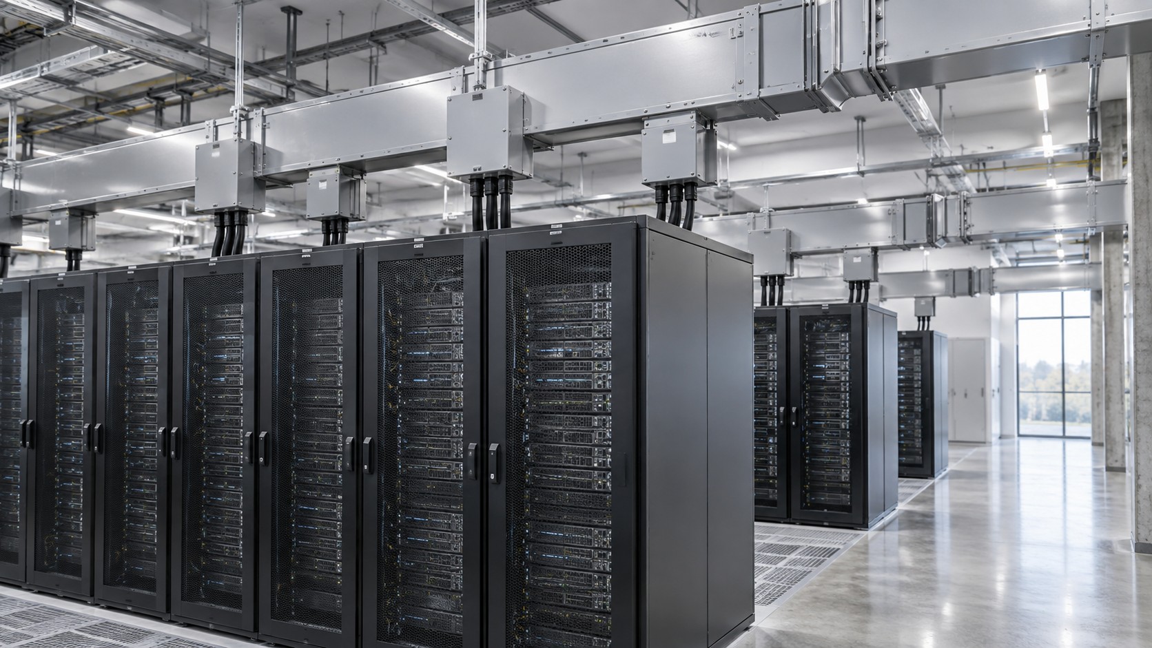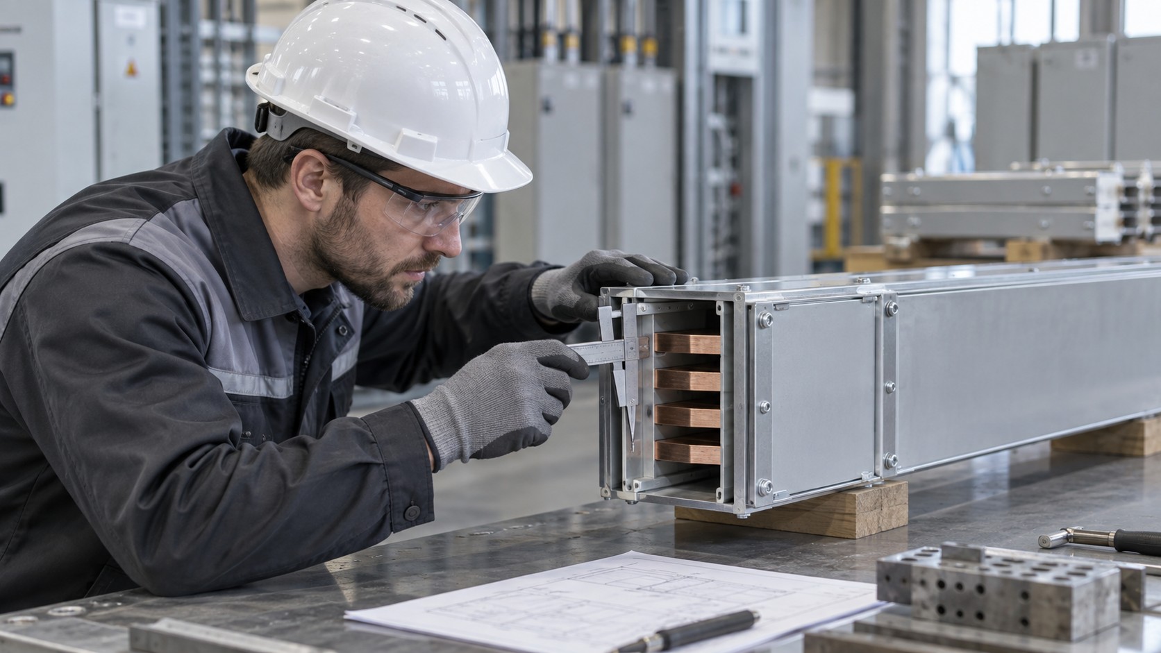
Busway and cable tray usually share the same riser, the same plant room and the same ceiling void, and they have almost nothing in common structurally. Busway needs independent support from the building frame and room to move; tray needs support spacing set by its load and fittings. Routing them together is a coordination exercise with fixed rules — and when those rules are broken, the failure appears as a hot joint, a distorted tray or a failed fire inspection.
Why combined routing needs its own design stage
Three properties differ between the two systems and drive every rule that follows:
- Support philosophy. A busway section weighs tens of kilograms per metre and is a proprietary assembly whose support spacing is a verified value under IEC 61439-6. A tray is a continuous beam carrying a distributed cable load under IEC 61537 or NEMA VE 1. Neither may be used to support the other.
- Movement. Busway has designed expansion and sliding sections; tray has expansion joints at different intervals and for different reasons. If they are mechanically linked, one system’s movement loads the other.
- Fire performance. Busway penetrations need a seal tested for the busway profile; tray penetrations need a seal tested for the tray. One oversized sleeve with both services inside has no test evidence unless a system has been tested that way.
Support separation: the rule that gets broken first
The busway must be supported from the building structure — slab, beam, or a steel frame designed for it — through brackets supplied or approved by the busway manufacturer. It must not be hung from cable tray, from sprinkler pipe, from ductwork, or from a trapeze that was sized for the tray. The reason is not bureaucratic: the busway’s support spacing is part of its design verification, and an unverified support introduces a load path the manufacturer never analysed.
Shared trapeze supports are acceptable only when an engineer has calculated the combined load, the anchors are rated for it, and both manufacturers accept the arrangement in writing. In practice this is rare in risers and common in plant rooms, where a single unistrut trapeze may carry a light tray and a small busway run.
| Arrangement | Acceptable? | Condition |
|---|---|---|
| Busway hung from cable tray | No | Never — the tray is not a structural member for this purpose |
| Tray hung from busway supports | No | Introduces unverified load into the busway bracket |
| Independent supports, common trapeze frame | Yes | Engineer’s calculation for combined load; both parties’ written acceptance |
| Separate trapezes at different levels | Yes | Preferred; check vertical clearance for cable access |
| Busway supported on tray support posts | Conditional | Only if the posts are designed as structure and the busway bracket matches the manufacturer’s detail |
Electrical separation between power and data
Where a data tray runs parallel to a busway, the separation distance is an EMC decision. EN 50174-2 provides separation tables based on the power circuit type, current and the length of parallel run; the values move from tens of millimetres for short runs at low current to 200 mm or more for long parallel runs at high current, and a metallic divider allows a reduction. Confirm the actual values against the current edition for your cable type and current — the principle is that separation is calculated, not guessed.
Busway is a concentrated source of magnetic field because the conductors are close together and the current is high. As a first-order indication only, the field from a single conductor at distance r is approximately B = μ0I / (2πr). For 1000 A at 0.3 m that gives about 670 µT before any cancellation between phases; a three-phase system cancels most of it at distance, which is why the manufacturer’s field data, not this formula, should be used. The formula is included to show why you do not route unshielded data cable against a 2000 A riser.
Practical measures, in order of preference: increase distance; interpose a steel divider or a steel tray side; use shielded or fibre data cable; and cross at right angles where a crossing is unavoidable.
Vertical shafts: the hardest coordination case
In a riser, the busway and the tray compete for the same few hundred millimetres. The working sequence that avoids most problems:
- Fix the busway line first. Its position is dictated by the tap-off access and by the structural supports; it has the least freedom to move.
- Reserve the tray zone with a defined clear dimension from the busway enclosure, not from the shaft wall, so that the EMC separation is measured from the right surface.
- Set the fire-stop strategy per service, with separate sleeves where the slab opening allows, and a tested combined seal only where a system exists for it.
- Coordinate expansion. Busway expansion sections and tray expansion joints should not coincide at the same floor if it can be avoided; if they must, both need access.
- Leave maintenance access. Busway joints need room for a torque wrench and an infrared camera; a tray bolted hard against the busway enclosure removes that access permanently.
Thermal interaction in a confined shaft
A tray full of loaded cables above a busway traps rising heat. The busway’s temperature rise was verified for a defined installation; adding a heat source above it changes the boundary condition. Keep the tray above the busway rather than below it where possible — hot air rises — and maintain the vertical clearance the busway manufacturer specifies. In a shaft with two busway risers and a tray between them, the middle position is the worst case for all three.
Application case: a hospital plant room and riser
Scenario constraints
A hospital extension has a main riser carrying a 1600 A busway to four floors of clinical space, with a 600 mm ladder tray for normal and essential services cables, plus a separate data tray. The riser is 2.4 m by 1.2 m, contains a sprinkler riser and a drainage stack, and every floor penetration is a fire compartment boundary requiring EI 90. The clinical floors cannot be shut down for later modifications.
Selection approach
The busway was positioned against the structural wall with its tap-off face accessible from the riser door, supported on floor brackets independent of everything else. The power tray was placed on the opposite wall at a higher level, with the data tray between them but offset vertically and fitted with a steel divider. Fire-stops were detailed as three separate tested seals rather than one combined sleeve. Expansion sections on the busway were set at levels 2 and 6, and tray expansion joints at the structural movement joint only, so the two never coincided. A 600 mm clear access strip in front of the busway joints was marked on the coordinated drawing and maintained on site.
Common mistakes in this configuration
- Routing the data tray through the gap between the busway and the wall, which is the highest-field position in the shaft.
- Cutting one large slab opening for all three services and sealing it with a single untested detail.
- Fixing the tray to the busway support brackets to save anchors, transferring tray load into a verified busway bracket.
- Leaving no space for the torque wrench, so joints are never re-torqued after the first year.
Acceptance points
Verify the separation distances on site with a tape, measured from the enclosure surfaces, not from centre lines. Confirm each service has its own labelled fire-stop with test reference. Check that no tray hanger is attached to a busway bracket. Confirm the busway expansion sections have visible travel and are accessible. Run a thermographic survey of the busway joints with the building at representative load, and check the tray for any point where cables rest on a fitting edge.
Coordination checklist for the design stage
- Draw both systems on one coordinated section at 1:20, not on separate drawings at 1:100.
- Fix the busway line and its tap-off access before routing the tray.
- Define the EMC separation from the busway enclosure surface, with the value taken from EN 50174-2 or the project EMC specification.
- Define fire-stop strategy per service, with test references.
- Define support independence in writing, and prohibit attachment between systems.
- Set expansion provisions so they do not coincide, or provide access if they do.
- Reserve maintenance access for joints, cameras and cable pulling.
Quality checks that catch coordination errors
Before the slab openings are cast, check the setting-out against the coordinated drawing — this is the last cheap moment to move a penetration. Before the busway is energised, confirm that no tray, conduit or pipe has been anchored to it since the last inspection. During the fire-stop inspection, check the seal depth and the substrate, and confirm the label matches the tested system for that service type. After energisation, thermography on the busway joints and a check of tray fill against the drawing will reveal most of what drawings cannot.
Working with suppliers on a combined route
Busway and tray usually come from different suppliers, and neither will accept responsibility for the other’s interface unless it is written down. Ask the busway supplier for the support and expansion drawings for the actual riser height, and for the minimum clearance to other services. Ask the tray supplier for the load-deflection data at your support spacing and the recommended spacing at fittings. Then put both sets of numbers on one drawing and issue it as the coordinated services layout — that single document prevents most of the failures described above.
Frequently asked questions
Can cable tray be fixed to busway supports?
No, not without an engineer’s calculation and the busway manufacturer’s written acceptance. The support spacing of busway is a verified value, and adding an unplanned load invalidates the basis of that verification.
How far should a data tray be from a busway?
The distance comes from the EMC separation tables applicable to the project — typically 200 mm or more for long parallel runs at high current, reducible with a metallic divider. Measure from the enclosure surfaces and confirm against the current standard edition.
Can both services share one fire-stop?
Only if a tested system exists for that combination, penetration size and substrate. Otherwise use separate seals. A combined opening sealed with mortar has no test evidence at all.
Which should be installed first?
The busway, because its position is constrained by tap-off access and structural supports. Reserving the tray zone afterwards is far easier than moving a manufactured busway run.
Does a tray above a busway affect its rating?
It can, by restricting convection and raising the local ambient. Keep the clearance the busway manufacturer specifies and avoid placing a loaded tray directly above a busway in a confined shaft.
How do I handle a crossing?
Cross at right angles, keep the maximum practicable distance at the crossing point, and avoid running parallel immediately before and after it. If the tray must drop below the busway, check the bend radius and the cable entry into any enclosure below.
Is a metal divider enough for EMC separation?
It allows a reduced distance where the applicable standard permits it, and it must be earthed to be effective. It does not remove the need to calculate the separation for the actual current and parallel length.
Plan the route once, with both systems on the drawing
BANGE Electric supplies busway systems with support and expansion drawings for the actual installation, and cable tray and ladder systems sized to the load and the environment. Send us the riser dimensions, the tray cable schedule and the fire strategy, and we will return a coordinated layout with the clearances marked. Contact us before the penetrations are cast. Requirements may vary by application, market, and applicable standard.