
Cable tray accessories are where a tray route either works or becomes a permanent compromise. The straight lengths are simple; the bends, tees, risers, reducers, and drop-outs are what determine whether cable goes in smoothly, whether bend radius is respected, and whether the route can be modified later. Specifying accessories as an afterthought is the single most common cause of site improvisation — and site improvisation on a cable route usually means a compromised bend radius or an unsealed joint. This guide covers each accessory type, what it does, and the specification points that matter.
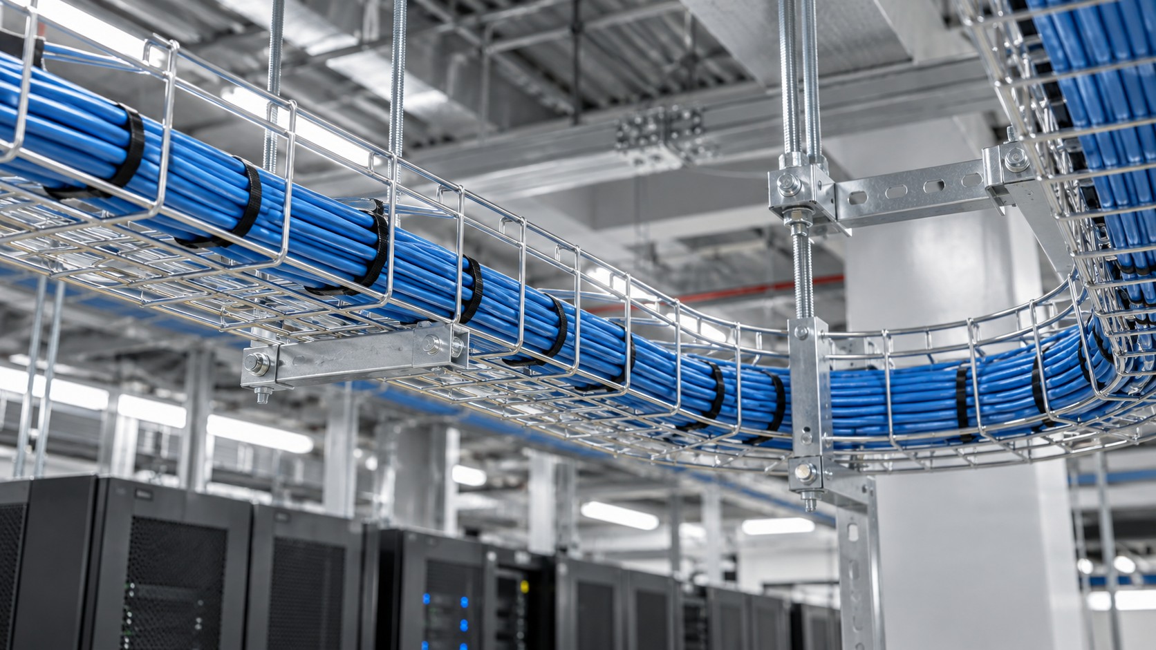
Horizontal Bends
A horizontal bend changes the route’s direction in plan. Available in standard angles — 90°, 45°, and 30° are common — and occasionally as adjustable or variable-angle units.
Specification Points
- Radius governs, angle doesn’t. The cable’s declared minimum bend radius is the constraint. A 90° bend and a 45° bend of the same radius are equally acceptable to the cable. Specify fittings by radius, and check that the radius meets the governing cable’s requirement.
- Match the tray type and finish. A bend must be the same type, width, and finish as the straight lengths — a galvanised bend in a stainless run is a corrosion site and a compatibility problem.
- Confirm sweep radius for large cable. Large-diameter power and armoured cable need a generous radius. Where space is tight, a larger-radius bend may not fit, and the route has to be redesigned rather than forced.
- Support on both sides. A bend concentrates load at its ends; support within a short distance of each end as the installation guidance requires.
Common Mistakes
- Ordering bends by angle only, discovering on site that the radius is too tight for the cable.
- Using a bend of a different type or finish from the straight run.
- Leaving bends unsupported at their ends.
Tees and Crosses
A tee branches the route at 90°; a cross branches in both directions. Both are used where the route divides.
Specification Points
- Branch radius matters too. The cable turning into the branch is bending just as much as it would in a bend. Confirm the fitting’s branch radius against the cable requirement — this is the most frequently overlooked radius on a route.
- Consider cable pulling direction. A tee is far easier to pull into than to pull through. Plan the pulling sequence around the fitting positions.
- Confirm the branch width. A branch narrower than the main run constrains the number of cables that can leave — and this becomes a permanent limitation on the route.
- Support the branch. A branch creates a load path that straight runs do not have; support it near the junction.
Vertical Risers and Elevation Changes
An inside riser changes elevation upward; an outside riser changes it downward. These are the fittings where bend radius problems most often become cable damage.
Specification Points
- The transition is the critical radius. Where a horizontal run turns vertical, the cable follows a curve whose radius is set by the fitting. Specify the riser by radius and confirm it against the cable’s minimum.
- Consider the pulling tension. Cable pulled up a riser is working against gravity as well as friction; a long vertical rise needs the pull planned, with intermediate pulling points where necessary.
- Secure cable in vertical runs. Cable in a riser tends to move downward under its own weight. Cleating or securing at intervals is required — a vertical run is not a place where cable can simply sit.
- Support the riser properly. Vertical sections carry their own weight plus cable weight; support at the intervals the installation guidance specifies.
Common Mistakes
- Checking the horizontal bends but not the riser transition — the tightest effective radius on many routes is at the base of a riser.
- Not securing cable in a vertical run, leading to gradual downward movement and stress at terminations.
- Underestimating pulling effort for a long vertical rise.
Reducers
A reducer transitions between two tray widths, used where the route narrows — typically as cables branch off and fewer continue.
Specification Points
- Use a symmetrical reducer where possible. An offset reducer changes the centreline, which complicates supports on both sides.
- Check fill at the narrow end. The reducer’s narrow side is the new governing constraint for the remaining cable — recalculate fill for that width, not for the original one.
- Confirm the transition does not create a cable-damaging edge. The narrower section must not present a sharp edge to cable being pulled through.
Drop-Outs and Cable Entry Fittings
Drop-outs allow cable to leave the tray downward or sideways to reach equipment, panels, or machinery.
Specification Points
- Protect the cable at the exit. The exit point is where cable is most likely to be damaged by an edge. Use a fitting designed for the purpose rather than cutting an opening in the tray.
- Confirm the exit radius. Cable leaving the tray is bending as it goes; the fitting must provide radius, not a corner.
- Position drop-outs before the tray is installed. Adding one later means cutting a loaded tray with cable in it — which nobody wants to do.
Couplers, Covers and Dividers
Couplers
Couplers join straight lengths and join lengths to fittings. Use the manufacturer’s coupler system rather than improvising, particularly where the tray serves as an equipment grounding conductor — the manufacturer’s coupler is the component whose electrical continuity has been tested.
Covers
Covers protect cable from falling objects, dust, and — where required — provide containment. Consideration: a cover reduces heat dissipation. Where a covered tray is densely loaded with power cable, the derating implication needs checking.
Dividers
A fixed divider separates cable categories within one tray — power from control, for example, where space does not permit two separate runs. Consideration: a divider reduces usable width, so fill must be calculated per compartment, not for the tray as a whole.
Accessory Selection Summary
| Accessory | Purpose | Key specification point | Most common error |
|---|---|---|---|
| Horizontal bend | Change direction in plan | Radius meets cable minimum | Ordered by angle, not radius |
| Tee / cross | Branch the route | Branch radius and branch width | Branch radius overlooked |
| Inside / outside riser | Change elevation | Transition radius; cable securing | Riser radius not checked |
| Reducer | Transition between widths | Recalculate fill at narrow end | Fill not recalculated |
| Drop-out | Cable leaves the tray | Protected exit with radius | Opening cut on site |
| Coupler | Join lengths and fittings | Manufacturer’s tested system | Non-matching coupler used |
| Cover | Protection and containment | Derating implication | Heat dissipation ignored |
| Divider | Segregate cable in one tray | Fill per compartment | Fill calculated for whole tray |
Application Case: Route With Multiple Direction Changes
Scenario Constraints
A route runs 70 m from a substation to a production line, with two 90° turns, an elevation rise of 3 m to a mezzanine, and four drop-outs to machinery. The largest cable is a 95 mm² armoured power cable with a substantial declared minimum bend radius. The route also carries control cable, segregated from power.
Approach
The governing dimension is the 95 mm² armoured cable’s minimum bend radius, applied at every one of the seven direction or elevation changes. Every bend, the riser transition, and each of the four drop-outs must provide at least that radius — the drop-outs especially, because a cable leaving the tray downward is bending at the point where it is also unsupported.
Fittings are specified by radius and ordered with the straight lengths, not after. Pulling is planned around the two 90° turns and the riser: cable is pulled toward the riser rather than through it where possible, and pulling tension is checked for the vertical section.
Drop-out positions are fixed before installation — located from the machinery positions on the drawing, not decided once the tray is up.
Segregation: where the route has space, power and control run in separate trays. Where a section is too tight for two runs, a divided tray is used for that section and fill is calculated per compartment.
Common Mistakes
- Checking bends but not drop-outs. Four drop-outs are four places where cable bends at an unsupported point.
- Ordering fittings after the straight lengths. Lead time forces either a delay or a site-made substitute.
- Not planning the pull around the riser. Pulling up a 3 m rise with two 90° turns already behind the cable is a different job from pulling on the flat.
- Deciding drop-out positions on site. Cutting a hole in a tray is the usual result, and it damages cable.
- Mixing fitting finishes or types into one run. Creates corrosion sites and continuity problems.
- Using a divider without recalculating fill. The tray is effectively narrower than its nominal width.
Acceptance Checks
- Every fitting’s radius verified against the governing cable’s declared minimum — including riser transitions, tee branches, and drop-outs.
- Fitting type, width, and finish confirmed as matching the straight run throughout.
- Support provided near each fitting, per the installation guidance.
- Cable secured in vertical sections at the required intervals.
- Drop-outs positioned as designed, with protected exits and no cut openings.
- Fill recalculated at reducers and at each compartment of divided sections.
- Earth continuity verified across every coupler and fitting where the tray forms the earth path.
Frequently Asked Questions
Can I cut an opening in the tray instead of using a drop-out?
You can, but you should not. A cut opening leaves an unprotected edge that can damage cable sheaths, provides no bend radius, and usually cannot be made safely once cable is installed. Use a purpose-made fitting.
Does the bend radius apply to tees as well as bends?
Yes. Cable turning into a tee branch is bending, and the branch radius must meet the cable’s declared minimum. This is the radius most often missed on a route.
Should fittings be ordered with the straight tray?
Yes. Fittings have lead times, and ordering them separately risks a delay or a site-made substitute. Determine the fitting schedule from the route drawing before ordering anything.
Can I use fittings from a different manufacturer?
Generally not advisable. Dimensions, radius, finish, and — where the tray is an earth path — electrical continuity are all system properties. Mixing products invalidates the verification.
Do covers affect cable rating?
They can. A cover reduces heat dissipation, so a covered tray with a heavy power load may require derating. Check the applicable guidance for the covered arrangement.
How do I handle a route that changes width partway?
Use a reducer at the transition, and recalculate fill for the narrower width — the reduced section becomes the governing constraint for the remaining cable.
Do vertical cable runs need special securing?
Yes. Cable in a vertical run is subject to gravity and will move downward over time, stressing terminations. Secure it at the intervals the applicable rules or the installation guidance specify.
Specify Your Cable Tray Route with BANGE Electric
BANGE Electric supplies cable tray with a full accessory range — bends, tees, crosses, risers, reducers, drop-outs, couplers, covers, and dividers — matched by type, width, and finish, with declared fitting radii so you can verify every change of direction before you order. Send us your route drawing and cable schedule, and we will return a complete fitting schedule.
Compare cable tray types or request a quotation.
Requirements may vary by application, market, and applicable standard. Figures given here are illustrative examples; always confirm against manufacturer data and your project specification.