
Cable sizing is the process of selecting a conductor cross-section that satisfies three independent requirements simultaneously: it must carry the load current without overheating, keep voltage drop within acceptable limits, and survive a short circuit long enough for the protective device to operate. All three must be checked, and the governing size is the largest one they produce. Undersized cable overheats, wastes energy, and can fail under fault conditions; oversized cable wastes money and copper.
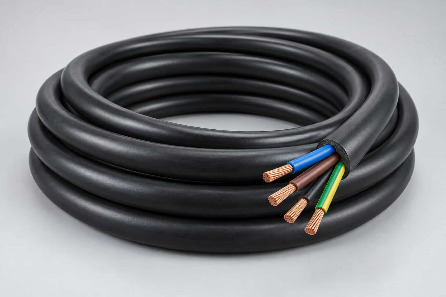
Why Cable Sizing Matters
Cable is one of the largest material costs in any electrical installation, which creates constant pressure to size it as small as possible. But the consequences of getting it wrong are severe and often appear years later.
Thermal damage is the primary risk. A conductor carrying more current than its rating will run hotter than its insulation is designed for, and insulation life roughly halves for every 8–10 °C of sustained excess temperature. Voltage drop is the second: excessive drop causes motors to run hot and lose torque, lighting to dim, and equipment to trip on undervoltage. Short-circuit withstand is the third, and the most dangerous — a cable too small for the prospective fault current can be destroyed before the breaker clears.
The Three Criteria
| Criterion | What it checks | Governed by | Typical limit |
|---|---|---|---|
| Current carrying capacity (ampacity) | Continuous current without exceeding insulation temperature limit | IEC 60364-5-52 / NEC 310 | 70 °C PVC, 90 °C XLPE |
| Voltage drop | Voltage at the load stays within limits | IEC 60364-5-52 / BS 7671 | 3% for lighting, 5% for power (typical) |
| Short-circuit withstand | Conductor survives until protection clears | IEC 60364-4-43 / IEC 60949 | k²S² ≥ I²t |
Step-by-Step Calculation
- Determine the load current. For a three-phase load: I = P / (√3 × V × PF × η). For single-phase: I = P / (V × PF). Use the actual equipment nameplate or the demand load with diversity applied.
- Select the protective device rating. The breaker or fuse rating must be at least the load current and must protect the cable.
- Look up the base current rating for the candidate cable size from the applicable table, based on conductor material (copper or aluminium), insulation type (PVC or XLPE), and installation method (in air, in conduit, buried, on tray).
- Apply correction factors for ambient temperature, grouping with other cables, soil thermal resistivity, and burial depth.
- Check the corrected rating against the protective device rating — this is the coordination check.
- Calculate voltage drop for the actual route length and confirm it is within limits.
- Check short-circuit withstand against the prospective fault current and the protection’s operating time.
- Select the largest size the three checks produce.
Base Current Ratings
Base ratings come from tables such as IEC 60364-5-52 Table B.52 (international) or NEC Table 310.16 (North America). They depend on installation method because heat dissipation varies enormously: a cable in free air cools far better than one buried in soil or buried in a conduit.
| Conductor (copper, XLPE) | In air on tray (approx.) | In conduit (approx.) | Buried direct (approx.) |
|---|---|---|---|
| 1.5 mm² | 24 A | 19 A | 26 A |
| 2.5 mm² | 32 A | 26 A | 34 A |
| 4 mm² | 42 A | 34 A | 44 A |
| 6 mm² | 54 A | 43 A | 56 A |
| 10 mm² | 75 A | 60 A | 76 A |
| 16 mm² | 100 A | 80 A | 99 A |
| 25 mm² | 133 A | 106 A | 127 A |
| 35 mm² | 164 A | 131 A | 152 A |
| 50 mm² | 198 A | 158 A | 180 A |
| 70 mm² | 253 A | 200 A | 219 A |
| 95 mm² | 306 A | 240 A | 259 A |
These figures are indicative for a single circuit at 30 °C ambient. They must be corrected for actual conditions and verified against the applicable standard for your market.
Correction Factors
| Factor | Effect on rating | Example |
|---|---|---|
| Ambient air temperature | Reduced above 30 °C | At 45 °C, derate to roughly 0.87 for XLPE |
| Grouping with other circuits | Reduced with more cables | 4 circuits bundled: often 0.7–0.8 |
| Solar radiation | Reduced for exposed outdoor runs | Apply manufacturer data for exposed tray |
| Soil thermal resistivity | Reduced for dry or rocky soil | 2.5 K·m/W vs 1.2 K·m/W materially changes size |
| Burial depth | Reduced for deeper burial | Beyond about 0.8 m, further derating |
| Harmonic content | Increased neutral current | Non-linear loads can require oversized neutral |
| Altitude | Reduced above 1000 m | Thinner air cools less effectively |
Note that factors multiply. A cable in a conduit at 45 °C grouped with three others may end up at roughly 0.6 of its base rating — which is precisely why simply reading a table and picking a size is unsafe.
Voltage Drop Calculation
Voltage drop for a three-phase circuit is calculated as:
ΔV = √3 × I × L × (R·cos φ + X·sin φ)
Where I is current, L is one-way route length in kilometres, R is resistance per kilometre, X is reactance per kilometre, and cos φ is the power factor.
Typical permitted limits under IEC 60364 and BS 7671 are 3% for lighting circuits and 5% for other uses, measured from the origin of the installation to the load. North American practice commonly uses 3% for branch circuits and 5% total for feeder plus branch.
Voltage drop, not ampacity, is frequently the governing factor on long runs. A 100 m feeder to a remote pump house can require a much larger cable than the load current alone would suggest.
Short-Circuit Withstand
The conductor must survive the fault current until the protective device clears. The adiabatic check is:
S ≥ (I × √t) / k
Where S is the minimum cross-section in mm², I is the prospective short-circuit current in amperes, t is the operating time of the protective device in seconds, and k is a material constant (approximately 143 for copper with XLPE insulation, 115 for copper with PVC, and 94 for aluminium with XLPE).
Practically, this means a circuit fed from a large transformer with a fast breaker may require a larger conductor than ampacity alone dictates. It is commonly overlooked on small circuits close to the source, where fault current is highest.
Worked Example
Size a three-phase 400 V cable for a 30 kW motor, power factor 0.85, efficiency 0.9, route length 60 m, installed on a cable tray with three other circuits, ambient 40 °C.
| Step | Calculation | Result |
|---|---|---|
| Load current | 30,000 / (√3 × 400 × 0.85 × 0.9) | 56.6 A |
| Protective device | Next standard size above load | 63 A MCCB |
| Base rating needed | 63 / (0.91 temp × 0.8 grouping) | 86.5 A |
| From table (in air, XLPE) | 16 mm² = 100 A | Sufficient |
| Voltage drop check | √3 × 56.6 × 0.06 × (1.24 × 0.85 + 0.09 × 0.53) | ≈ 5.8 V = 1.45% |
| Within 5% limit? | 1.45% < 5% | Yes |
| Short-circuit check | Assume 10 kA, 0.1 s, k=143: S ≥ 1000 × 0.316 / 143 | S ≥ 2.2 mm² — 16 mm² fine |
| Selected size | Largest of the three | 16 mm² |
Common Mistakes
- Ignoring grouping factors. Cables on a crowded tray run hotter than the table assumes.
- Forgetting voltage drop on long runs. This is the most common reason a “correct” size is wrong.
- Skipping the short-circuit check. Small circuits near a large transformer are at particular risk.
- Using the wrong installation method column. In-conduit and in-air ratings differ by 20% or more.
- Assuming aluminium and copper are interchangeable. Aluminium needs a larger size and compatible terminations.
- Ignoring harmonic loads. VFDs and switch-mode supplies can push neutral current above phase current.
- Not documenting the calculation. Cable schedules should record the basis for every size selected.
Relevant Standards
- IEC 60364-5-52 — selection and erection of wiring systems, current-carrying capacity
- IEC 60364-4-43 — protection against overcurrent
- IEC 60287 — calculation of the continuous current rating of cables
- IEC 60949 — calculation of thermally permissible short-circuit currents
- BS 7671 — UK wiring regulations, widely used internationally
- NEC Article 310 — conductors for general wiring (North America)
Frequently Asked Questions
1. Which criterion usually governs cable size?
For short runs, ampacity. For long runs — typically beyond 50–80 m — voltage drop. For circuits close to a large transformer with high fault current, short-circuit withstand.
2. Can I use a smaller cable if the load is intermittent?
Only with a properly documented duty-cycle assessment. Standard tables assume continuous load; intermittent duty may permit a smaller size, but the calculation must be recorded.
3. Does cable size affect the protective device?
Yes, and the relationship is bidirectional. The device must protect the cable, and the cable must have sufficient rating for the device. Both directions must be checked.
4. How does ambient temperature change things?
Ratings in tables are usually based on 30 °C ambient air. Above that, derate; below, a modest increase may apply. Local standards define the exact factors.
5. Should I oversize for future load?
Often yes, but deliberately and with documentation. Adding 20–30% margin at installation is far cheaper than replacing cable later.
6. Is aluminium cable acceptable?
Yes for larger sizes where terminations and jointing are properly handled. It requires a larger cross-section than copper and compatible lugs to avoid galvanic corrosion.
7. How do harmonics affect sizing?
Non-linear loads generate third-order harmonics that add in the neutral. In worst cases the neutral conductor must be sized equal to or larger than the phase conductors.
Plan Your Cable Installation with BANGE Electric
Cable sizing directly determines the cable tray, conduit, and support system your project needs. BANGE Electric supplies cable tray and support systems sized to your cable schedule, and can review your routing layout to confirm the tray width and support spacing accommodate the cables you have calculated.
Contact us with your cable schedule and routing plan — we will respond within 24 hours with a proposal and quotation.
Requirements may vary by application, market, and applicable standard. Final specification should be confirmed with the engineering team.