
Busbar sizing determines the cross-sectional area of a copper or aluminium conductor needed to carry a given current without exceeding its allowable temperature rise. Unlike cable, a busbar is a bare or insulated bar in air or in an enclosure, so its rating depends on surface area, orientation, enclosure ventilation, and proximity of other bars in addition to cross-section. Getting the size right matters because it drives the cost, weight, and physical dimensions of switchgear, busway, and distribution equipment.
What Is a Busbar?
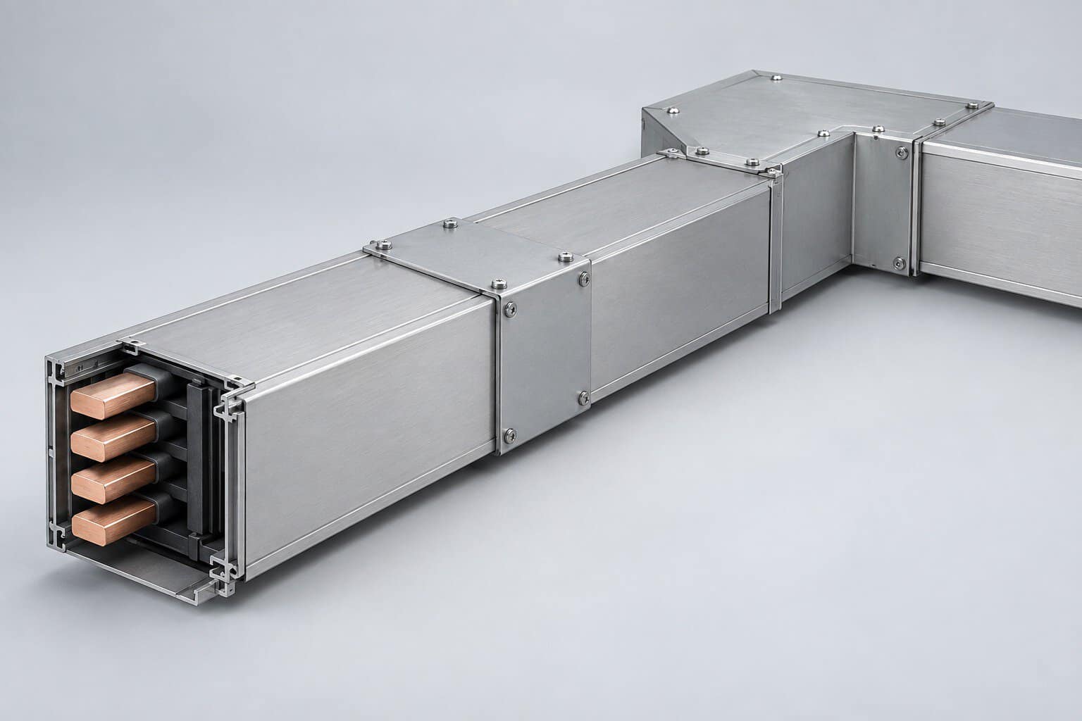
A busbar is a rigid conductor — a flat bar, rod, or shaped profile — used to collect and distribute electric power within an assembly or between items of equipment. Busbars are found inside switchgear, panel boards, motor control centers, and as the conductors inside a busway system. Compared with cable of equivalent rating, a busbar has a much larger surface-area-to-volume ratio, which is why it dissipates heat more effectively and is preferred at high currents.
Why Busbar Sizing Differs from Cable Sizing
Cable sizing relies on published ampacity tables derived from standardized test conditions. Busbar sizing is more of an engineering calculation, because the rating depends heavily on geometry choices the designer controls:
| Factor | Effect on rating |
|---|---|
| Cross-sectional area | Larger area carries more current, but not linearly |
| Surface area (perimeter) | Heat dissipation scales with exposed surface, not area |
| Orientation | Flat bars on edge cool better than flat bars laid flat |
| Number of bars per phase | Multiple stacked bars cool worse than a single bar |
| Enclosure | Ventilated enclosures allow higher ratings than sealed ones |
| Surface finish | Dark or painted surfaces radiate heat better than bright metal |
| Altitude | Thinner air reduces convective cooling above 1000 m |
The Heat Balance Principle
A busbar reaches a steady temperature when the heat it generates equals the heat it loses. Heat generated is I²R — proportional to the square of current and to resistance. Heat lost occurs by convection to the surrounding air and by radiation from the surface.
Because heat loss scales with surface area while heat generation scales with volume, simply doubling the cross-section does not double the rating. Doubling the thickness roughly increases the rating by about 1.5 times, not 2 times. This is why high-current busbars are often built from several thin bars stacked with air gaps rather than one thick bar — the gaps add cooling surface.
Empirical Sizing Formula
A widely used rule of thumb for copper busbar in free air, at a 35–40 °C permissible temperature rise, is:
I ≈ 1.2 × A^0.5 × P^0.25 × k (empirical, indicative only)
Where I is current in amperes, A is cross-sectional area in mm², P is perimeter in mm, and k is an enclosure/orientation factor. Because this is empirical and varies between sources, it should be used only for preliminary sizing; final ratings must come from the equipment manufacturer’s type-test data.
A simpler practical approximation used in many design offices for copper bar in air: roughly 1.2 to 1.6 A per mm² for smaller bars (up to about 500 mm²), falling to about 0.8 to 1.0 A per mm² for very large sections. Aluminium is roughly 60–70% of the copper figure for the same section.
Typical Busbar Ratings (Copper, Indicative)
| Bar size (mm) | Cross-section (mm²) | Single bar, on edge (A) | Two bars per phase (A) |
|---|---|---|---|
| 25 × 3 | 75 | ≈ 300 | — |
| 25 × 5 | 125 | ≈ 420 | — |
| 40 × 5 | 200 | ≈ 600 | ≈ 1,050 |
| 50 × 5 | 250 | ≈ 720 | ≈ 1,280 |
| 50 × 10 | 500 | ≈ 1,150 | ≈ 2,000 |
| 80 × 10 | 800 | ≈ 1,600 | ≈ 2,800 |
| 100 × 10 | 1,000 | ≈ 1,900 | ≈ 3,300 |
| 2 × (100 × 10) | 2,000 | — | ≈ 4,800 |
These are indicative values for bare copper in free air with a dark surface finish. Enclosed busbar ratings are lower; manufacturer type-test data always governs.
Busway Ratings
In a busway (bus duct) system, the busbars are enclosed, so the rating depends on the enclosure design as much as on the conductor. IEC 61439-6 covers busbar trunking systems and requires type testing of the complete assembly — the enclosure, insulation, joint design, and conductor together determine the rating.
| Busway rating | Typical conductor | Typical application |
|---|---|---|
| 250–630 A | Single copper bar or sandwich construction | Commercial risers, small plants |
| 800–1600 A | Sandwich or air-insulated bars | Industrial plants, mid-size facilities |
| 2000–3200 A | Multiple bars per phase, ventilated housing | Large industrial, data centers |
| 4000–6300 A | Heavy multi-bar, often cast-resin or high-density | Utility, heavy industry, large data centers |
For a full comparison of busway constructions, see our guide on busway system types and selection.
Skin Effect and Proximity Effect
At power frequency (50/60 Hz), alternating current does not distribute uniformly across a conductor’s cross-section. Skin effect pushes current toward the surface; proximity effect pushes it away from adjacent conductors carrying current in the opposite phase. Both reduce the effective conducting area and increase the AC resistance above the DC value.
Skin effect becomes significant for copper bars thicker than about 10–12 mm. This is another reason high-current designs use multiple thin bars instead of one thick bar: it mitigates skin effect as well as improving cooling.
Proximity effect matters when phases are close together, which is common in compact sandwich busway designs. Type testing captures the combined effect, which is why tested ratings for enclosed systems should always be used in preference to calculated free-air values.
Short-Circuit Withstand
Busbars must survive the electromagnetic forces and thermal stress of a fault. During a short circuit, parallel bars carrying current in opposite directions repel each other with enormous force, proportional to the square of the peak current.
Two checks are required:
- Thermal withstand — the bar must not exceed its temperature limit before protection clears, using the same adiabatic principle as cable: S ≥ (I × √t) / k.
- Mechanical withstand — the busbar supports and bracing must resist the peak electromagnetic force. Support spacing is reduced for high fault levels, and insulators are rated for the resulting bending moment.
IEC 61439 requires verification of short-circuit withstand by type test or by comparison with a tested design. This is one of the most important reasons to buy assemblies from a manufacturer with valid test documentation.
Derating Factors
| Condition | Typical effect |
|---|---|
| Enclosed in a ventilated housing | Rating reduced by roughly 10–25% vs free air |
| Enclosed in a sealed housing | Reduction can reach 30–40% |
| Ambient temperature above 35 °C | Reduce rating or upsize conductor |
| Altitude above 1000 m | Derate progressively; significant above 2000 m |
| Many bars per phase closely stacked | Each additional bar adds less than the first |
| Direct solar exposure outdoors | Additional derating per manufacturer data |
Worked Example
Select a copper busbar for a 1600 A switchboard main bus, enclosed in a ventilated cubicle, ambient 40 °C.
| Step | Calculation / Decision | Result |
|---|---|---|
| Required rating | Full load with margin | 1600 A |
| Free-air requirement | Apply enclosure factor ≈ 0.8 and ambient derate ≈ 0.95 → 1600 / (0.8 × 0.95) | ≈ 2100 A free-air equivalent |
| Candidate | 2 bars of 80 × 10 per phase | ≈ 2,800 A free air |
| Margin check | 2,800 × 0.8 × 0.95 = 2,128 A > 1,600 A | Acceptable |
| Short-circuit check | Assume 65 kA for 1 s, k = 143: S ≥ 65,000 × 1 / 143 | S ≥ 455 mm² — 1,600 mm² provided, fine |
| Selected | 2 × (80 × 10) copper per phase | Confirmed by type test |
The final step is the one that matters: the selected arrangement must appear in the manufacturer’s type-tested configuration for the assembly.
Common Mistakes
- Using free-air ratings for enclosed busbar. This is the single most common error and can oversize the rating by 30%.
- Ignoring skin effect on thick bars. A single 20 mm bar performs worse than two 10 mm bars of the same total area.
- Forgetting mechanical bracing. Thermal withstand is checked but the supports are not rated for the fault forces.
- Overlooking joint resistance. Bolted joints are the most likely point of overheating; torque and surface preparation matter enormously.
- Mixing metals without protection. Copper-to-aluminium joints need bimetallic transition washers or plating to prevent galvanic corrosion.
- Skipping altitude derating. Projects above 2000 m require meaningful reduction.
How to Inspect Busbar Quality
- Verify the bar dimensions and material against the approved drawing.
- Check plating at joint surfaces — tin or silver plating should be continuous and bright.
- Confirm joint torque values against the manufacturer’s specification and look for torque markings.
- Check support and bracing spacing against the tested design.
- Perform a millivolt drop test across joints to detect high-resistance connections.
- Confirm the assembly carries a type-test certificate covering the rated current and short-circuit withstand.
Frequently Asked Questions
1. Why does a busbar carry more current than a cable of the same area?
Because it has a larger surface area for the same cross-section, so it dissipates heat better. It also has no thick insulation layer trapping heat.
2. Can I just use current density rules like 1 A/mm²?
Not for final design. Current density rules give a rough starting point only, because rating depends on perimeter, orientation, enclosure, and arrangement as much as on area.
3. Is aluminium busbar as good as copper?
Aluminium is lighter and cheaper but has about 60% of copper’s conductivity, so it needs a larger section. It also requires careful joint design and compatible plating.
4. How does enclosure type change the rating?
A ventilated enclosure typically costs 10–25% of free-air rating; a sealed enclosure can cost 30–40%. Always use type-tested values.
5. What causes busbar joints to overheat?
Mostly insufficient torque, oxidised or contaminated contact surfaces, and dissimilar metal contact. Correct preparation and torque, verified with a drop test, prevent most failures.
6. Do busbars need derating at altitude?
Yes. Above 1000 m, thinner air reduces convective cooling, and the manufacturer’s derating curve should be applied.
7. Which standard covers busbar sizing?
IEC 61439-1 and IEC 61439-2 for assemblies, IEC 61439-6 for busbar trunking, and UL 857 for busways in North America. IEC 60439 is the withdrawn predecessor still seen on older documentation.
Source Busbar Systems from BANGE Electric
BANGE Electric supplies busway systems with type-tested current ratings per IEC 61439-6, in ratings from 250 A to 6300 A, with conductor, joint, and enclosure designs verified as a complete assembly rather than estimated from free-air calculations.
Contact us with your load profile, fault level, and route layout — we will respond within 24 hours with a sizing proposal and quotation.
Requirements may vary by application, market, and applicable standard. Final specification should be confirmed with the engineering team.