
Cable tray fill capacity is the maximum amount of cable a tray can carry while remaining safe, maintainable, and compliant. It is governed by two independent limits: the physical cross-sectional area the cables occupy, and the mechanical load the tray can support. Exceeding either one causes overheating, sagging, or difficulty adding cables later. This guide explains how to calculate both, the relevant NEC and IEC rules, and the mistakes that most often cause trays to be undersized.
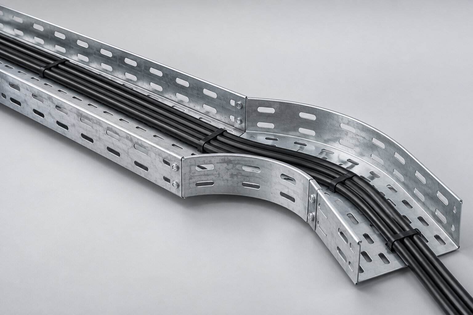
What Is Cable Tray Fill Capacity?
Fill capacity answers a deceptively simple question: how many cables of a given size can you put in a tray of a given width? The answer is not just geometric. Two separate constraints apply, and the governing one is whichever binds first.
The first is the area limit — cables must not occupy more than a set fraction of the tray’s usable cross-section, so air can circulate and heat can escape. The second is the load limit — the total weight of the cables must not exceed what the tray and its supports can carry over the chosen span.
Why Fill Capacity Matters
Undersizing a tray is one of the most expensive errors in electrical installation, because it is discovered late — usually during commissioning, when the last cables will not fit — and the fix means replacing the supports and re-pulling cable.
Overfilling has three concrete consequences. Heat builds up because cables stacked in a confined space cannot dissipate it, which accelerates insulation ageing and can force derating below the circuit’s requirement. Mechanical load grows, causing the tray to sag between supports and, in the worst case, to fail. And maintainability collapses: a tray packed to its limit cannot accept a single additional cable without a shutdown and a re-lay.
The Two Limits You Must Both Satisfy
| Limit type | What it constrains | Governed by | Typical check |
|---|---|---|---|
| Area / fill | Sum of cable cross-sectional areas vs tray usable area | NEC 392 (US), IEC 61537 (intl.) | Percentage of tray width occupied |
| Mechanical load | Total cable weight per metre vs rated load | Manufacturer span/load tables, NEMA VE 1 | kg/m against rated load at the chosen span |
| Span deflection | Maximum sag between supports | NEMA VE 1 (typically L/200) | Measured deflection under load |
How to Calculate Fill Capacity: Step by Step
- List every cable with its overall diameter and weight per metre, taken from the manufacturer’s datasheet — not from the conductor size alone, since insulation and armouring add significantly.
- Calculate each cable’s cross-sectional area using its overall outside diameter: area = π × (d/2)².
- Sum the areas for all cables intended for that tray.
- Determine the tray’s usable cross-section: internal width × usable depth (typically the side rail height, minus a small allowance at the top).
- Apply the applicable fill rule for your standard and cable type (see below).
- Check the load separately: total cable weight per metre × span, compared against the rated load at that span.
- Add margin — industry practice is to size for 20–25% spare capacity for future circuits.
NEC 392 Rules for Cable Tray Fill
In North America, NEC Article 392 sets maximum fill by tray type and cable size. The rules differ because large power cables need air around them, while small control cables can be bundled more densely.
| Tray type | Cable type | Maximum fill rule |
|---|---|---|
| Ladder or ventilated tray | Large power cables (over 1000 kcmil / approx. 500 mm²) | Single layer, cable diameter spacing maintained |
| Ladder or ventilated tray | Power cables up to 1000 kcmil | Sum of cable diameters must not exceed tray width |
| Ventilated trough | Control and signal cables | 50% of cross-sectional area |
| Solid bottom tray | Any cable | 40% of cross-sectional area |
| Any tray | Cables 1/0 AWG and larger | Installed in a single layer in most cases |
The IEC Approach
IEC 61537 covers cable tray systems internationally and is primarily a mechanical and safety standard rather than a fill-percentage standard. Under IEC-based designs, the fill is usually determined by the project specification, the cable manufacturer’s derating data, and national wiring rules — for example BS 7671 in the UK or local regulations elsewhere.
The practical method under IEC-based practice is to space single-core power cables by at least one cable diameter, or to apply the derating factors supplied by the cable manufacturer for grouped cables in trays. This is why the cable schedule and manufacturer data matter more than a single universal percentage.
Worked Example
Suppose a 300 mm wide ladder tray must carry twelve 4-core 35 mm² power cables, each with an overall diameter of 26 mm and a weight of 1.8 kg/m.
| Step | Calculation | Result |
|---|---|---|
| Cable cross-sectional area | π × (26/2)² | 531 mm² each |
| Total cable area | 531 × 12 | 6,372 mm² |
| Tray usable area | 300 mm × 100 mm rail height | 30,000 mm² |
| Area fill | 6,372 / 30,000 | 21% — acceptable |
| Width check (NEC style) | 26 mm × 12 = 312 mm vs 300 mm width | 312 > 300 — too narrow |
| Load check | 1.8 kg/m × 12 = 21.6 kg/m vs rated load | Compare to span table |
Note the outcome: the area check passes easily at 21%, but the width check fails. This is exactly why the two checks are both necessary — a tray that looks only 21% full geometrically can still be too narrow under the diameter-sum rule, because large cables need spacing for heat, not just area.
The fix here is to move to a 400 mm tray, or to split the cables across two runs.
Factors That Reduce Usable Capacity
- Cable diameter growth — armoured cables and those with thicker insulation take far more space than the conductor size suggests.
- Spacing requirements — single-core power cables often need a diameter of clear air between them, which can halve effective capacity.
- Future circuits — designing to 100% fill leaves no room for expansion.
- Support span — a longer span reduces the allowable load even though the tray width is unchanged.
- Fittings — bends, tees, and risers have less usable area than straight sections and often become the real bottleneck.
- Mixed cable sizes — mixing large and small cables wastes space because the large ones dictate spacing.
Tray Type and Usable Capacity
| Tray type | Pros for capacity | Cons for capacity |
|---|---|---|
| Ladder | Best ventilation, strongest for heavy loads, long spans | Rungs may not suit very small cables without a mat |
| Perforated | Supports small cables, good containment | Slightly less ventilation than ladder |
| Wire mesh | Flexible, easy to cut, good for data cabling | Lower load rating, not for heavy power cables |
| Solid bottom | Maximum protection, best for EMC separation | Lowest fill allowance (typically 40%), worst heat dissipation |
Common Mistakes
- Using conductor size instead of overall diameter. A 35 mm² conductor is not 35 mm across — 4-core cable of that size is typically 24–28 mm overall.
- Ignoring the load limit. A tray can be within its area fill and still be overloaded by weight.
- Sizing for today only. Leaving zero spare capacity guarantees an expensive retrofit.
- Forgetting the fittings. A horizontal bend constrains more than the straight run feeding it.
- Mixing power and data without a divider. This reduces usable width and creates interference risk.
- Assuming the same fill for every tray type. Solid bottom trays have a lower allowance than ladder.
How to Inspect Fill on Site
- Compare installed cable count against the approved tray schedule.
- Confirm large power cables are in a single layer with the specified spacing.
- Check that no cable is stacked on top of another in a way that traps heat.
- Measure deflection at mid-span under full load; compare against the rated limit.
- Verify spare capacity is physically present for the documented future circuits.
Frequently Asked Questions
1. What percentage fill is allowed in a cable tray?
It depends on tray type and cable size. Under NEC 392, ventilated tray carrying power cables is limited by the sum of cable diameters rather than a percentage, while solid bottom trays are typically limited to 40% of cross-sectional area. Always confirm against your local code.
2. Can I stack cables in a tray?
For large power cables, generally no — they should be in a single layer. Small control and instrumentation cables may be layered within the area limit, but stacking reduces heat dissipation and should be minimized.
3. How much spare capacity should I design for?
A minimum of 20–25% is common practice for industrial facilities. Data centers and plants with frequent layout changes often design for 40–50% spare.
4. Does fill capacity affect ampacity?
Yes. Closely packed cables dissipate heat poorly, so derating factors apply. This is why spacing rules exist alongside the geometric fill rules.
5. Do bends and tees reduce capacity?
Yes. Fittings have less usable width and force cables to converge, so they frequently govern the design even when straight sections have margin.
6. Can I add cables to an existing tray later?
Only if spare area, spare load capacity, and physical access all still exist. This is precisely why initial sizing should include margin.
7. Which standard should I use?
NEC Article 392 and NEMA VE 1 in North America; IEC 61537 internationally, together with your national wiring rules and the cable manufacturer’s grouping derating data.
Source Cable Tray Systems from BANGE Electric
BANGE Electric supplies ladder, perforated, wire mesh, and solid bottom cable trays with documented span and load ratings, so fill calculations can be checked against real data rather than estimates. Our engineering team can review your cable schedule and confirm the required tray width, depth, and support spacing.
Contact us with your cable list and routing layout — we will respond within 24 hours with a sizing proposal and quotation.
Requirements may vary by application, market, and applicable standard. Final specification should be confirmed with the engineering team.