
Conduit and cable tray are the two most common ways to route and protect electrical cables in commercial and industrial buildings. Conduit is a closed tube that fully encloses cables, offering maximum mechanical and environmental protection. Cable tray is an open support system that carries cables in air, offering easier access, better heat dissipation, and lower installed cost for large cable counts. The right choice depends on cable quantity, ampacity, environment, and how often the installation will be modified.
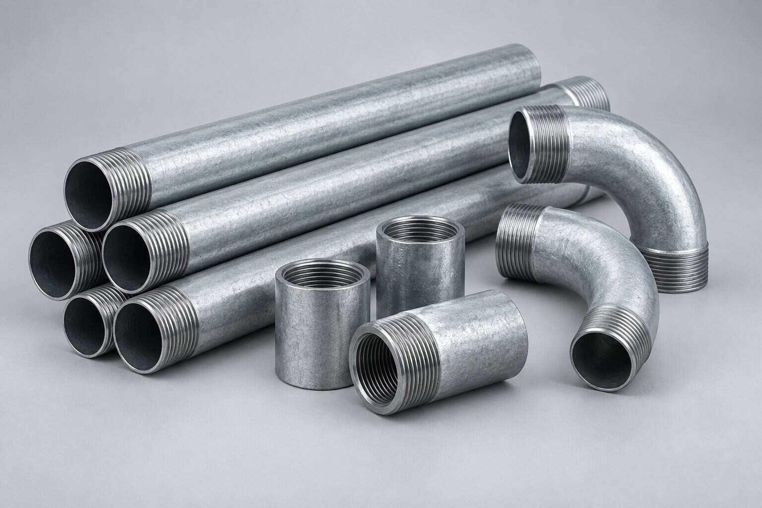
What Is Electrical Conduit?
Electrical conduit is a closed raceway — a tube or pipe — through which individual cables are pulled after the conduit itself is installed. Conduit is installed first, then cables are drawn through using a fish tape or pulling rope. Because the cables are fully enclosed by a continuous wall, conduit provides the highest level of mechanical protection available in standard electrical installation practice.
Conduit systems are governed by IEC 61386 (conduit systems for cable management) internationally and by NEC Chapter 9 in North America. The fill percentage — how much of the conduit’s internal cross-sectional area may be occupied by cables — is strictly limited, typically to 40% for three or more conductors, because pulling cables through a tightly packed tube causes insulation damage.
What Is a Cable Tray?
A cable tray is an open support system consisting of a continuous base — ladder rungs, perforated sheet, wire mesh, or solid bottom — with side rails, supported by brackets from the ceiling, wall, or floor. Cables are laid into the tray rather than pulled through it, which makes installation dramatically faster for large cable counts and makes future additions trivial.
Cable trays are covered by IEC 61537 internationally, NEMA VE 1 in North America, and NEC Article 392. Because cables sit in open air rather than inside a tube, they dissipate heat more effectively, which often allows a smaller conductor cross-section for the same current.
For a full breakdown of tray types, see our guide on cable tray types, uses and selection.
Conduit vs Cable Tray: Key Differences
| Feature | Conduit | Cable Tray |
|---|---|---|
| Structure | Closed tube, fully encloses cables | Open support system, cables exposed |
| Cable installation | Pulled through with fish tape | Laid in from above |
| Mechanical protection | Very high | Moderate |
| Heat dissipation | Poor — cables bundled in a tube | Good — cables in open air |
| Ampacity derating | Significant for many conductors | Minimal |
| Typical fill limit | 40% of internal area (NEC Ch.9) | Per NEC 392 or IEC 61537 spacing rules |
| Cost at low cable count | Lower | Higher (support hardware) |
| Cost at high cable count | Much higher | Lower |
| Future additions | Difficult — often new conduit | Easy — lay another cable in |
| Visual appearance | Hidden in walls/slabs or surface-mounted | Visible, typically overhead |
| Applicable standard | IEC 61386 / NEC Chapter 9 | IEC 61537 / NEMA VE 1 / NEC 392 |
Types of Electrical Conduit
Rigid Metal Conduit (RMC)
Heavy-wall steel or aluminum tube with threaded connections. RMC offers the highest mechanical protection and can be used as an equipment grounding conductor. Typical in exposed outdoor runs, hazardous locations, and where physical damage is likely.
Electrical Metallic Tubing (EMT)
Thin-wall steel tube with compression or set-screw fittings. Lighter and cheaper than RMC; widely used indoors in commercial buildings. Not suitable for direct burial or severe physical exposure in most jurisdictions.
Intermediate Metal Conduit (IMC)
A middle ground — lighter than RMC but with thicker walls than EMT, threaded like RMC. Common in industrial plants where EMT is too light and RMC is overkill.
PVC Conduit
Non-metallic, corrosion-resistant, and easy to cut and join with solvent cement. Standard for underground burial and corrosive environments. Requires a separate equipment grounding conductor and has lower temperature rating than steel.
Flexible Conduit (FMC / LFMC)
Used for short connections to vibrating equipment such as motors and transformers, and where a rigid run cannot be routed. Liquid-tight flexible conduit adds a waterproof jacket for wet locations.
Types of Cable Tray
Ladder Cable Tray
Two side rails connected by transverse rungs at regular intervals. The strongest type for long spans and heavy power cables, with the best ventilation. Standard in industrial plants and for large-diameter power cables.
Perforated Cable Tray
Solid sheet bottom with punched ventilation slots. Better support for small-diameter cables and more containment than ladder, with moderate ventilation. Common for control and instrumentation cables.
Wire Mesh Cable Tray
Welded steel wire construction. Lightweight, easily cut on site, and highly flexible for routing changes. Popular in data centers and for low-voltage and data cabling.
Solid Bottom Cable Tray
Continuous sheet with no perforations. Used where maximum protection from falling debris, dust, or electromagnetic interference is required, at the cost of heat dissipation.
Heat Dissipation and Ampacity: Why It Matters More Than You Think
This is the single most overlooked factor in the conduit-versus-tray decision. When multiple current-carrying conductors are bundled inside a conduit, each cable’s heat adds to the others, and the trapped air cannot carry it away. Electrical codes address this with ampacity derating (adjustment) factors.
As a practical illustration of the principle: under NEC Table 310.15(C)(1), four to six current-carrying conductors in a raceway require the ampacity to be adjusted to 80% of the table value; seven to nine conductors drop that to 70%. In a cable tray, cables installed in a single layer with spacing per NEC 392 rarely require such adjustment beyond the rules for the specific cable type.
The consequence can be material. A circuit that needs 95 A might be satisfied by a 25 mm² conductor in a cable tray but require 35 mm² — or a larger conduit to reduce derating — if run in a crowded conduit. On a project with hundreds of circuits, that difference compounds into real money and real copper weight.
Installation Cost and Labor
| Scenario | Conduit | Cable Tray |
|---|---|---|
| 1–3 circuits, short run | Cheaper — minimal hardware | Overkill |
| Many parallel power cables | Very expensive — many parallel tubes | Much cheaper — one shared tray |
| Frequent future changes | Expensive to modify | Cheap to modify |
| Labour skill required | Bending, threading, pulling | Cutting, supporting, laying |
| Support spacing | Close — typically every 1.5–3 m | Wider — typically 1.5–3 m but fewer pieces |
The crossover point depends on local labour rates and material costs, but the general rule holds: conduit wins for few cables, tray wins for many.
Common Applications
Conduit Is Typically Preferred For
- Underground and buried runs — PVC or galvanized RMC protects against soil load and moisture.
- Concealed installation — inside walls, slabs, and ceilings where tray would be inaccessible.
- Hazardous or explosive atmospheres — sealed conduit prevents flame propagation.
- Short drops and final connections — from a tray to a motor or panel.
- High physical damage risk — vehicular areas, loading docks, exposed outdoor walls.
Cable Tray Is Typically Preferred For
- Industrial plants — long runs of power and control cables with frequent future changes.
- Data centers — huge volumes of data and power cabling needing constant reconfiguration.
- Commercial high-rise risers and corridors — main distribution runs.
- Oil, gas and petrochemical facilities — where large cable counts and maintenance access dominate.
- Infrastructure — tunnels, water treatment plants, and transit facilities.
How to Choose: A Practical Decision Sequence
- Count the cables and estimate future growth. Fewer than about four circuits usually favours conduit; more favours tray.
- Check the environment. Buried, concealed, corrosive, or explosive locations push toward conduit.
- Calculate derating. Determine whether conduit fill will force you to upsize conductors; if so, tray may be cheaper overall.
- Consider access needs. Facilities that change layout frequently strongly favour tray.
- Check the code and the client standard. Some clients mandate conduit for certain circuits regardless of cost.
- Review the structural path. Tray needs support points; verify the ceiling or wall structure can carry the load.
Can You Combine Conduit and Cable Tray?
Yes, and most real installations do. The common pattern is a cable tray carrying the bulk of the distribution, with conduit used for drops from the tray down to individual items of equipment. The transition point needs a proper fitting: a tray-to-conduit transition plate that protects the cables from abrasion at the edge, plus bushings on the conduit end.
Two rules to respect at the transition. First, do not exceed the conduit fill limit for the cables entering it. Second, support the conduit independently — a tray is not designed to carry the weight of a vertical conduit drop.
Installation Best Practice
- Keep spacing between cables in tray where code requires it, to preserve ampacity.
- Do not overload the tray — respect the manufacturer’s rated load and the span rating.
- Secure cables at regular intervals, especially on vertical runs where gravity pulls cable down.
- Separate power and data cables — use a divider or separate tray to avoid electromagnetic interference.
- Bond and ground metallic tray sections continuously; do not rely on bolted joints alone.
- Protect against abrasion at every tray-to-conduit transition and at sharp bends.
How to Inspect Quality Before Acceptance
- Check the tray finish — hot-dip galvanizing should be continuous, with no bare spots at cut edges or welds.
- Verify support spacing against the approved drawing and the manufacturer’s span rating.
- Confirm every metallic section is bonded and that the grounding path is continuous.
- Measure coating thickness on galvanized tray with a digital gauge; compare against the specified minimum.
- Inspect conduit runs for kinks, excessive bends (more than 360° between pull points is a problem), and proper bushing.
Frequently Asked Questions
1. Can cable tray replace conduit entirely?
Rarely. Conduit is still required for buried runs, concealed runs, final connections to equipment, and hazardous locations. Most facilities use tray for the bulk of distribution and conduit for drops and special locations.
2. Does cable tray need to be grounded?
Yes. Metallic cable tray must be bonded and grounded as an equipment grounding path or with a separate equipment grounding conductor, depending on the applicable code and the tray’s listing.
3. How many cables can I put in a cable tray?
It depends on cable diameter and tray width. NEC 392 sets rules based on cable size and tray type; IEC 61537 addresses load capacity. As a working rule, leave visible spacing between large power cables and never exceed the tray’s rated load.
4. Is conduit always safer than cable tray?
Conduit offers better mechanical protection, but tray offers better heat dissipation and easier inspection. In many industrial installations, tray is the safer overall choice because overheating from derating is avoided and faults are easier to locate.
5. Can I run data and power cables in the same tray?
Only with a solid divider separating them, and only if the data cable is rated for the voltage present. Many standards require separation to prevent interference and to protect low-voltage circuits.
6. What is the maximum fill for conduit?
Under NEC Chapter 9 Table 1, 53% for a single conductor, 31% for two conductors, and 40% for three or more. Local codes vary; always confirm against the applicable standard.
7. Which is cheaper for a typical plant expansion?
For an expansion with many new circuits, cable tray is almost always cheaper because a single tray run replaces many parallel conduits and can be modified without demolition.
Source Cable Management Systems from BANGE Electric
BANGE Electric supplies cable tray systems — ladder, perforated, wire mesh, and solid bottom — in galvanized steel, stainless steel, and aluminium, along with the supports and fittings required for a complete installation. Whether your project calls for tray, conduit, or a combination, our engineering team can review your cable schedule and propose a routing that meets the applicable standard.
Contact us with your single-line diagram, cable list, and site conditions — we will respond within 24 hours with a layout proposal and quotation.
Requirements may vary by application, market, and applicable standard. Final specification should be confirmed with the engineering team.